I’ve always wanted to make a time lapse video. It’s like building a machine to catapult forward in time. What could be more fun? I really feel like the best time lapse videos integrate camera motion to give the scene an additional compelling dimension. I spent a couple of evenings building a quick and dirty motorized camera slide from a dead inkjet printer. It was a failure. It was unable to produce the slow steady motion needed for video, much less the kind of control needed for time lapse. I started to think about what a serious system with substantial time investment would have. It could be bigger and have at least two-axis camera motion. It would need a bunch of software with some way of key-framing the camera motion, maybe an LCD display, maybe a pendant control for stepping/snapping frames without jiggling the camera. What else? A way to power and auto-trigger the camera for time lapse. All in all a much, MUCH bigger project. OK, if that’s the end goal, what’s a good first step? I’m always wary of physically big projects. As the size goes up, costs go up. Big projects are harder to get into/out of the car, take up more workbench space, and ultimately collect dust in a bigger way. If I can fit a project into a single project box, life is simpler.
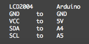
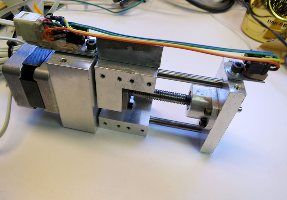
 So instead of embarking on a large two- or three-axis rig, I decided to build a very small one-axis rig. Heck, I already had a small one-axis slide. This way I could get my feet wet with the software, LCD, motor controllers, and all the other fun stuff, but without as much schlepping. A friend of mine pointed out that a little motorized stage like that could also be used for focus stacking, and he’d been wanting to build a focus stacking rig. He sent me little linear slide with a stepper motor drive and a tiny ball screw. I’d never seen a ball screw that small! It was sweet! I poked around on Amazon and ordered a A4988-based stepper motor driver the size of a postage stamp. They were cheap, small, and the data sheet made them sound like they were doing a decent job with the microstepping, which might be useful for very precise focus stacking. I used to build stepper motor drivers out of discrete components, but it’s unbelievable what you can get these days for not much money. I’ve been itching to try some of the pre-made ones out, so I ordered the stepper motor and a much bigger driver board based on the TB6560, mostly because I was having trouble convincing myself that a driver without a heat sink was really going to be able to do the job. And even the big one was cheap. It was less than $17, including two-day shipping to my door. I’d also been wanting to play with some of these cheap LCD displays I see around, so I ordered a 4-line 20-character blue one that Amazon Primed its way to my house for $16. I ordered the blue one because a green-and-black LCD was going to make the project look like it was from the early 90’s. I ordered one that had an I2C daughter board because I wasn’t sure how many IO pins this project was going to need, and I didn’t really want to burn half of them driving the display. When the display came, I was bummed that they’d shipped me the green and black version, not the blue one! I set my time machine for the early 90’s and kept moving. I wired up the display to an Arduino Uno. I downloaded the Arduino IDE and a library to drive the display. I wired it up like this:
Then I ran this exciting bit of code.
#include <Wire.h>
#include <LiquidCrystal_I2C.h>

//Addr: 0x3F, 20 chars & 4 lines
LiquidCrystal_I2C lcd(0x3F,20,4);

void setup()
{
 lcd.init();
 lcd.backlight();
 lcd.setCursor(0, 0);
 lcd.print("Hello World");
}

void loop()
{
}
 Thankfully, it just worked. The text was super crisp and readable.
I was still a bit bummed about the color, so I decided to roll the dice and try ordering the blue display again. I’d be able to compare the two colors side-by-side and see which one I liked best. This time I did get the blue one. It worked and was crisp and clear. Our eyes don’t like focusing on dark blue things though, and if I had to be brutally honest I’d have to say that the green display was more readable. I decided to switch to the blue one anyway.
 I wrote a little program to page through all 256 characters that could be sent to the display to see what sorts of special characters might be available. There were a few useful ones like left and right arrows, the deg symbol, and a solid block character which I might actually use in my interface.
The next step was to put the various parts I was thinking about using together to visualize how things were going to fit.

I was originally going to mount everything to the side of the motorized stage so I could cut down on external wiring. I could even put the end-of-travel sensors inside the project box. But it was starting to look 10 pounds of project in a 5-lb bag.
The project box was big, and it was going to have to be right under the camera or using it would be uncomfortable and trying to manipulating it would jiggle the camera. Those issues seemed like deal breakers. The next plan was to put the control box at some distance from the motor and make a separate control pendant that could plug in. I’d need OK and Cancel buttons and some sort of spring-loaded pot for jog control.
 I went poking around at the local surplus store and scored a VCR remote with a nice spring-loaded jog wheel. It even had two buttons inside the wheel, so I thought my control pendant problems where over. I’d wire up the jog wheel/buttons through a phone connector to the main control box, and I’d be all set. However, when I dissected the remote, I found that the jog wheel was not a pot. It had 3 digital pins providing gray code position info. That meant only a few jog speeds in each direction, and it meant I’d need more lines than a standard phone cord. Back to square one.
 I decided to take a stab at adding my own spring to a pot to make a “return to center” jog controller. I drilled a hole through the pot’s shaft and bent up a spring. It worked. After some fiddling, I was able to make it control the motion of the slide. It had a really sloppy feel to it. The center was always just kind of approximate, and it was harder to turn in one direction than the other. Kind of a cruddy experience compared to the feel of the remote’s nice jog wheel. I decided to punt for a while and work on other parts of the project.
 I wired up the end-of-travel sensors. I was using IR gap sensors for a no-contact way of measuring the travel. Now that the sensors couldn’t be mounted inside the project box, I decided to make them fit inside a bit of metal wiremold that I had lying around. I used some Bondo to hold the sensors at the correct height and support a phone jack at the end so the sensors could be easily connected up.
This was by far the most annoying part of the entire build. The phone jacks turned out to be back-stabbing fiends. Fitting everything in the wiremold was annoying, and I had a wire tear out when I was closing it up. Then the sensors weren’t working, so I ripped everything apart trying to figure out why. I had accidentally grabbed a two-conductor phone cord even though I’d purchased a 4-conductor one. Then when I finally figured that out, I failed to realize that when using phone connectors, the wires get flipped from left to right so red on one end becomes green on the other, and black becomes yellow. *Smack Forehead* After I figured that out, I thought I was home free, but it still didn’t work. I finally traced the problem to a poorly designed jack where the connector could clip in, but was still not fully seated and wasn’t making contact. After that got resolved, everything was fine. But I’d burned an entire afternoon trying to run 4 wires a few feet.
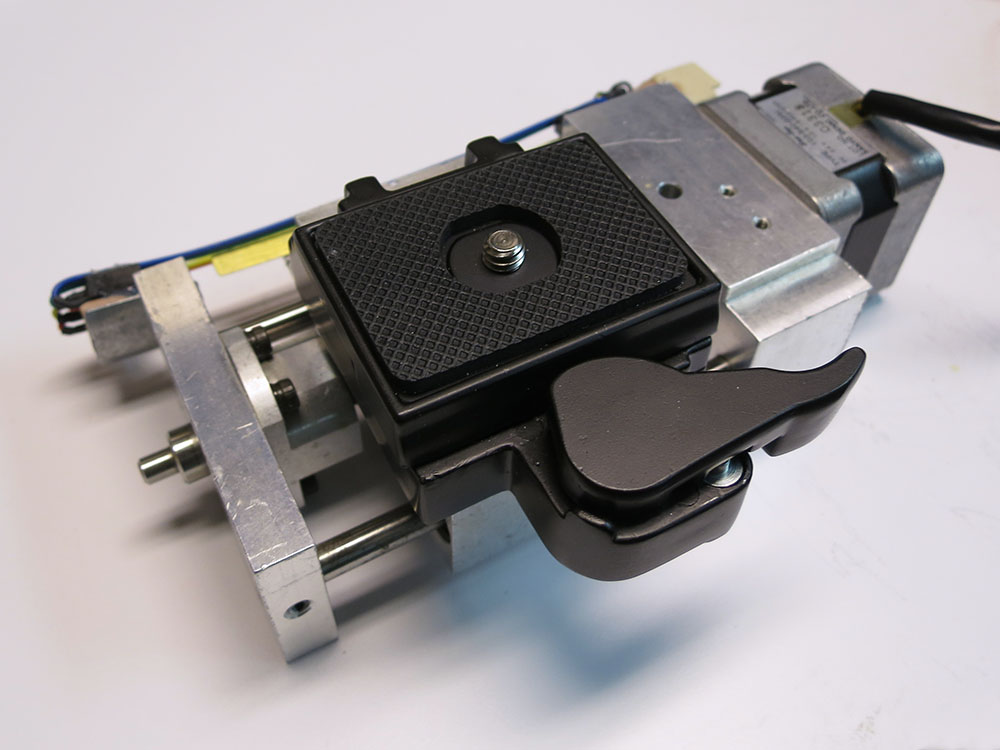
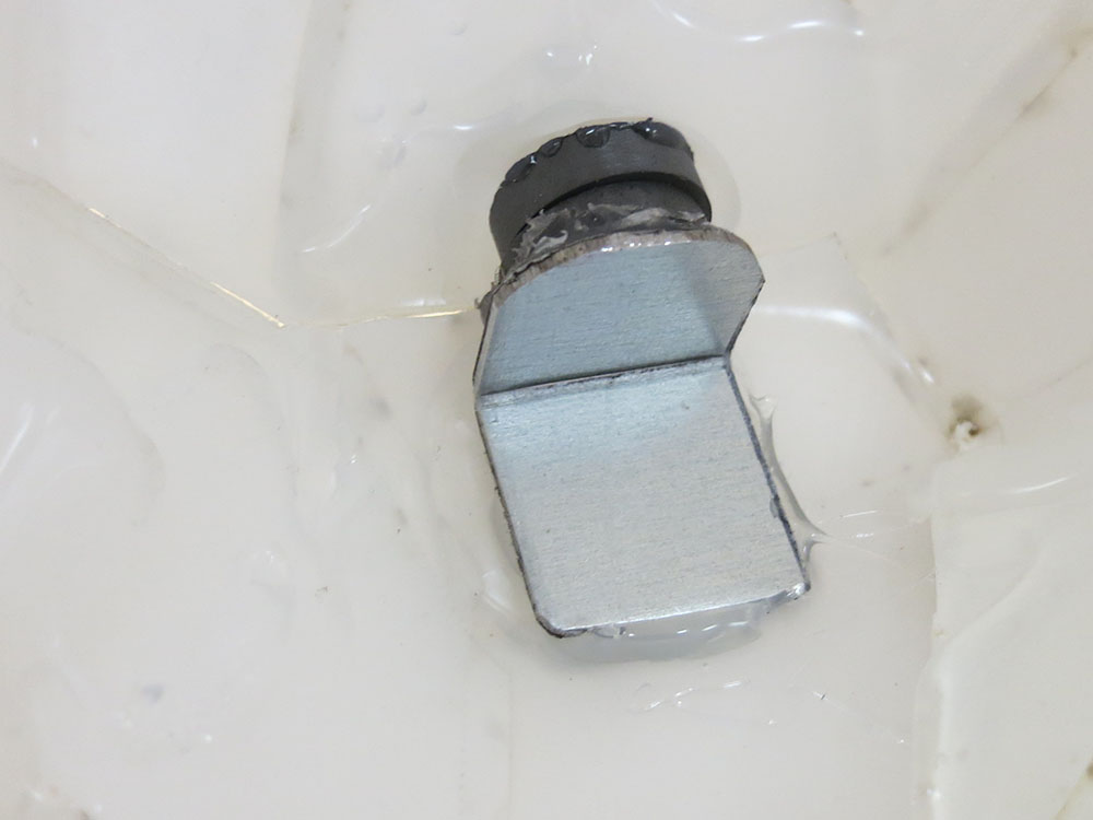
 I got a super cheap quick-release plate. When I was taking it out of the packaging, a spring and pin fell right out of the bottom. I deemed them to be unnecessary and threw them out. Then I noticed that the cam lock tends to slowly unscrew and the screw can’t actually be tightened properly without making the cam hard to turn. A dab of Loctite could solve that. Hey, it was cheap! My only regret is that I wasn’t able to mount it so the cam stuck out the same side as the wiremold. This would have made the whole thing more compact left to right, but that might have required tapping some blind holes, and this way around it was simple to mount. Just a 1/4-20 though an already existing hole in the carriage.
 I had all this wired up to an Arduino Nano. It could jog the motor when I twisted the pot, and it could read the end-of-travel sensors. Next was to start designing some UI for the LCD. I played around with being able to highlight various menu options by quickly toggling the solid block character behind them, etc. It all seemed doable, but it was kind of tedious Arduino development. I kept thinking “How is this going to scale up for multi-axis key frame animation craziness?”
Massive Feature Creep Occurs
It was then that I noticed Bluetooth LE boards for the Arduino. Could I control my whole rig from an iPhone app? I could ditch the LCD, buttons, pendants, and all the associated wires and connectors. I could make the project box smaller. I could write an iPhone app to do the interface heavy lifting, and I’d only have to do a moderate amount of stuff on the Arduino end of things. No more planning out of awkward LCD interfaces. Plus, it just sounded fun!
 So I ordered one of the boards, and I was off to the races. Adafruit’s page about wiring up the board is very clear, and I hooked up an Arduino UNO just to try it out. I was able to get their UART echo communication going right away. Simple, Pimple.
The next test would be to write my own program to establish the Bluetooth communications and see if I could use a slider to jog the motor. I wanted to test the latency and to see if stepper motor switching noise would affect the communications.
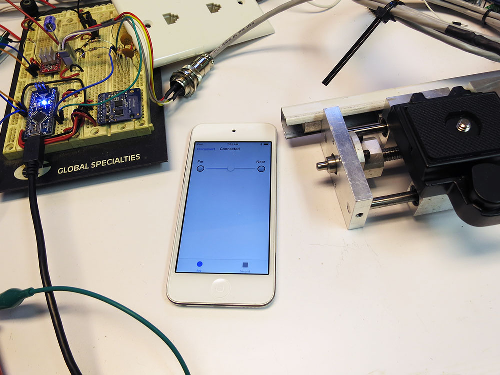
The great thing about Bluetooth LE is that you don’t need any special licensing. I spent one of my precious Wednesday nights ripping the com parts out of the Adafruit example and sticking them into my own simple app. The app just had a connect/disconnect button, a connection status indicator, and two end-of-travel indicators. The communication is only 9600 baud, so I made a special jog loop the Arduino could go into where the phone would keep sending single bytes of jog slider info, and a 0 would indicate that the jog portion was done and go back to the main loop.
The very first version wasn’t wired to anything. It would just indicate end-of-travel limits having been reached if you slid the slider close to the end of its travel path. After tracking down an issue with a rough signed char, I got it working. The latency was quite low.
 Next up: rewire the Nano to remove the LCD/knob and wire in the Bluetooth LE board. Then I’d be able to jog an actual motor. I powered it up and could hear the motor making some ticking sounds, but jogging wasn’t working. I went to hook up the scope and bumped the alligator clip that was providing motor power. It touched something on the board, and the Arduino’s LED’s went out. Yup, I’d fried the Nano. Ouch. Oh dear. Had I fried the USB port on my computer? Apparently not. *phew* No need to panic. I did not, however, have a spare Nano on hand. Trying out the jogging was going to have to wait until next week.
 In the mean time, I rewired some parts of the protoboard to make it a bit less hairy. I don’t want accidental short circuits killing things, but I also don’t like clipping the leads on resistors and caps. When the replacement Nano came, I decided to only connect motor power after I was reasonably sure the other things were working. I used the oscilloscope to see if the Nano was producing the expected step pulse trains.
Yup, that seemed to be working. With some trepidation, I decided to try and hook up motor power again. Nothing burned out, and it worked! Next I needed to see if the limit switches worked. I jogged the stage all the way down to the end, and one of my limit indicators on the iPhone started flickering like crazy. But it was the wrong indicator. I swapped near/far sensors and added some software switch debouncing. The slow linear ramp of the limit sensor was producing a lot of noise when it got close to the logic level boundary. I’d love to run it into a nice Schmitt Triggered gate. That would keep the software nice and clean, but if I was going to have PCBs made, it would add area and expense.
I could have made them go-to-analog inputs and just used two thresholds. That’s probably what I should have done, but stepping at 1/16 of a step was putting me at 54400 steps per inch, which was really taxing the powers of the accellStepper library and I didn’t want to add much to my inner loop. That’s probably silly of me and adding two analog reads to my loop wouldn’t matter. Instead, I did digital reads and required a large number of matching consecutive answers before alerting the iPhone. Probably over complicating the code since the real bottleneck in accellStepper is probably its use of millis() not a couple of analog reads.
 Next up was to install CHDK on my camera and see if I could manage to use a USB cable to act as a remote shutter switch. CHDK runs on various Canon cameras and lets them do things they normally couldn’t. My camera (a Canon S100) didn’t have a way of remote triggering, so I had to hack it with CHDK to do that. You have to make a special bootable SD card. I used a tool called STICK to analyze a photo taken by my camera, determine the exact firmware in the camera, and download and format a bootable SD card. This made setting it up simple. Then I went through a maze of menus to turn on remote shuttering. I wired one of the Nano’s output pins to my camera’s USB port and wrote a snippet of code to take a picture. It worked! Right now I hold a line high for 1 second, and then it takes a photo when the line goes low. I haven’t tried running a shorter cycle. Maybe with manual focus/metering it could take photos more quickly. I haven’t tried.


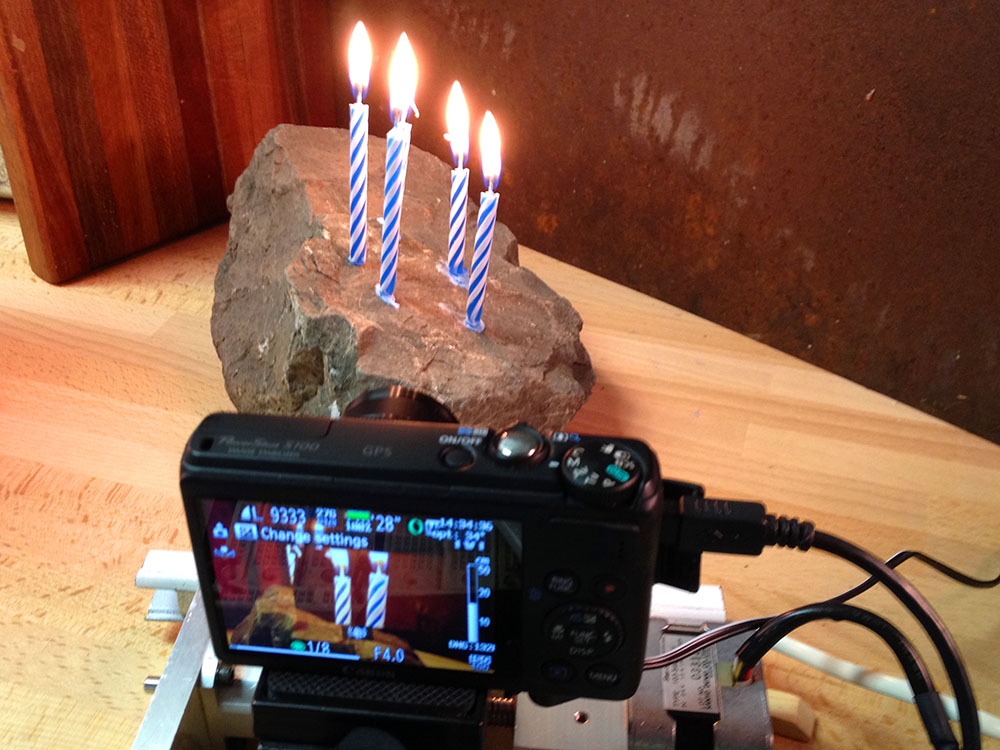
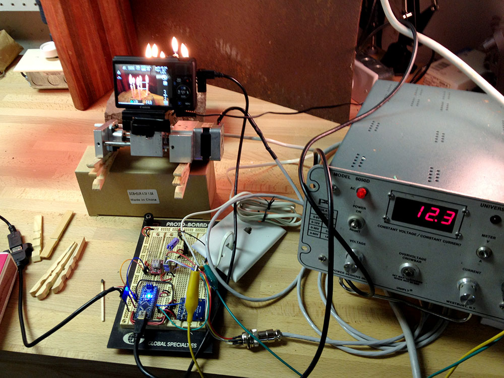
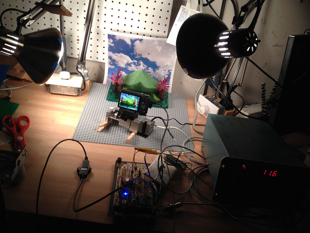
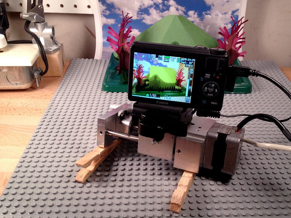
I had motion, I had photo taking. It was time to try and do a time lapse with this rig. I took it over to my son’s Lego studio area and set up a magic crystal garden I’d purchased online. I used fun-tack and clothespins to aim the rig, plunked an old calendar photo of clouds in the background, and we were almost ready to go. I set all the camera settings to manual. Then I set the code to move though the system’s full range of motion over 10 hours, taking one frame every 2 minutes for a total film length of 10 seconds.
I waited until it was dark, and I fired off the time lapse. It felt like Christmas Eve, and I didn’t know if Santa was going to leave me a time-travel movie or a lump of coal. I told the kids we couldn’t go into the garage for 10 hours. In the morning, I went out to see what had happened. The first thing I noticed was that one of the big chunks of foam I’d taped up over the garage windows had fallen down during the night. Oh, oh. Still, the crystals were fully grown and there were 300 photos on the camera, so it was time to try and play them as a movie. Unfortunately, iMovie only lets you specify still frames down to 0.1 seconds in length, so you can’t really make a 1/30 of a second one-frame-per-image movie. Argh! Photoshop can do it, but that requires loading all the frames into layers. On my machine, loading in 300 big 3000×4000 pixel images was taking for-ev-er. Finally, I just downloaded some freeware frame encoding tool and used that to build my time lapse. Then I could use iMovie to add title, fiddle with the sound, etc. By 11am, I’d finally managed to unwrap My First Time Lapse. It was over-exposed and didn’t have great focus, but the kids thought it was cool. Success!


 This year Simon requested a Pokemon costume, specifically a Bulbasaur. I was glad his costume was going to be made of cloth, since his brother’s costume required no tailoring. I really look forward to Halloween as a time to release my inner seamstress.
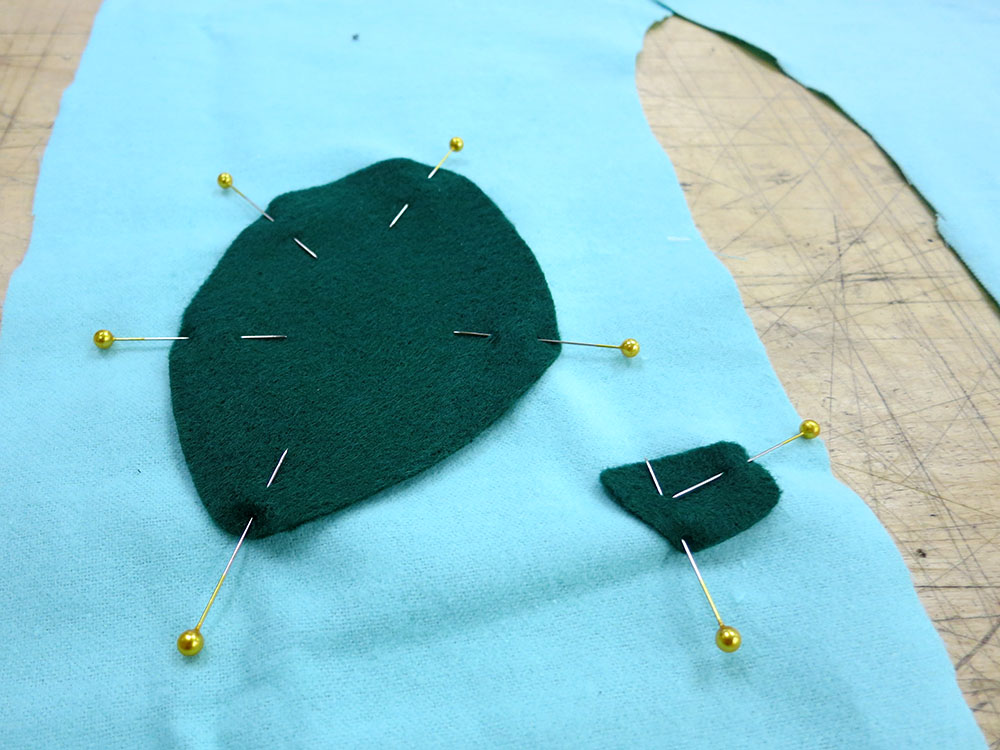 I chose fairly accurate colors for the body and spots, but I went for a more organic-looking material for the bulb. Something a little less GREEN. I also got some dark brown corduroy because I was hoping to make the bulb a functional backpack, which required a dark liner.
 When I was making the toes for the pants, I realized I hadn’t brought any polyester fiber fill. I wasn’t going to waste an hour going to the fabric store to get some, so I just used my scissors to cut up some shreddies of material to fill the toes. It wasn’t as even as fiber fill, but the toes are small enough that it didn’t really matter.

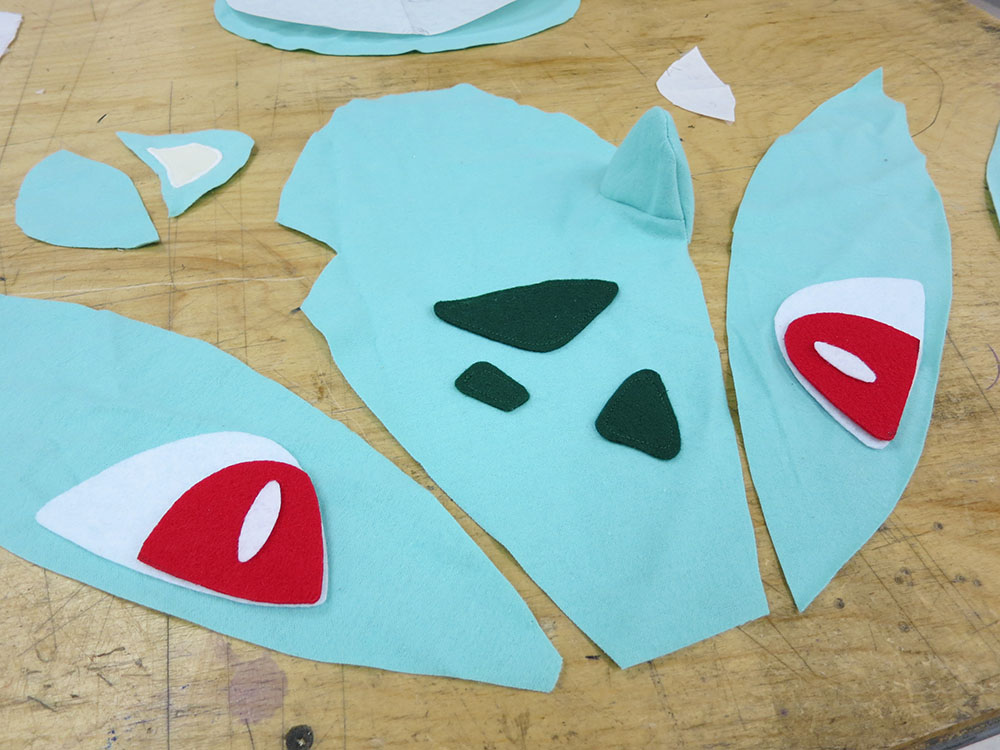
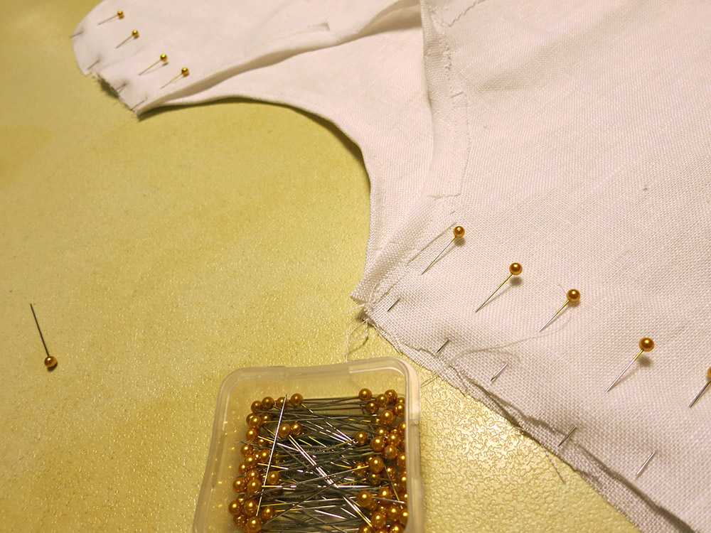
 Actual Bulbasaurs don’t have a different inner ear color, but I added a cream triangle inside the ear to make the ears stand out and be a bit cuter. I used a very tight zig zag stitch to sort of embroider a wide line around the ear inserts, which was necessary because I didn’t have felt for that and I needed something to hem the cut edges of the cloth. I also thought it looked more cartoon-like than folding under the edges.
 I used the same system to put the dark green lines around the eyes. That was a bit hair-raising because at those slow feeds it’s easy to have the boarder bog down and drift away from the edge. I only had one shot. The second eye border came out better than the first.
 I put the pieces together and sewed it onto the hat. Then I stuffed and shaped it with fiber fill. I was really pleased with the way the hat came out. One of the TechShop employees even recognized it as a Bulbasaur, so I knew I was in the zone. Much better than “that frog thing.”
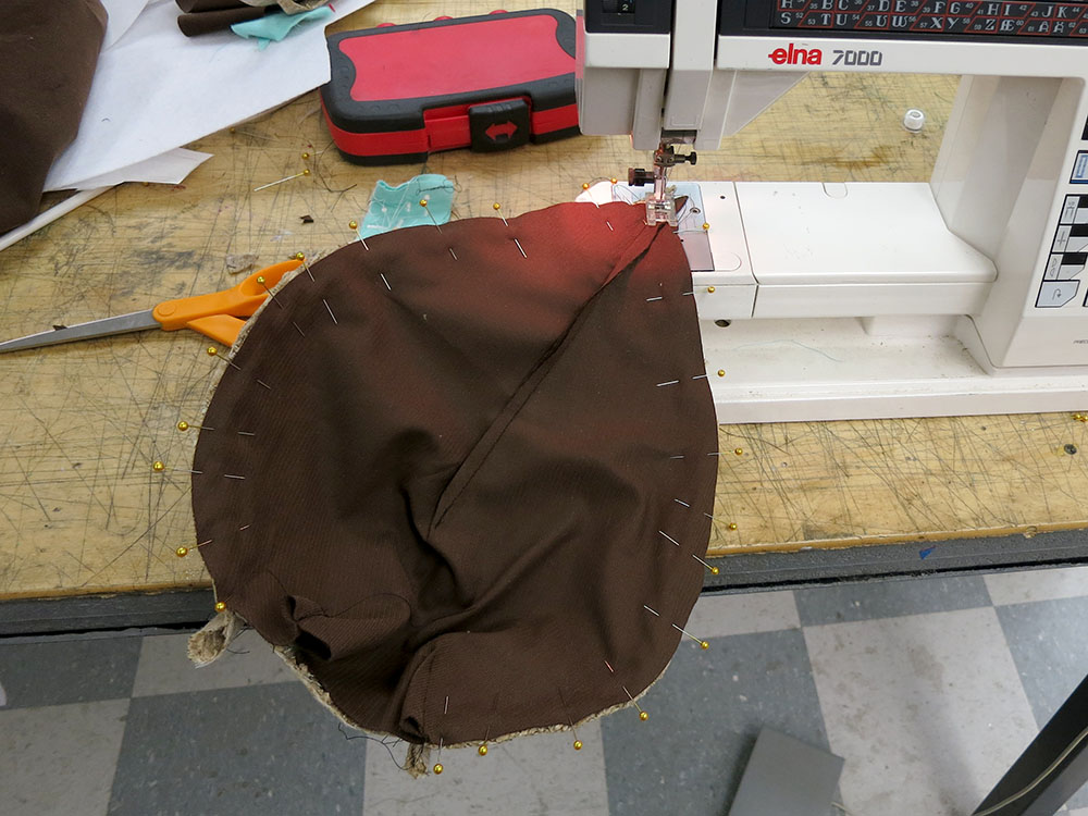
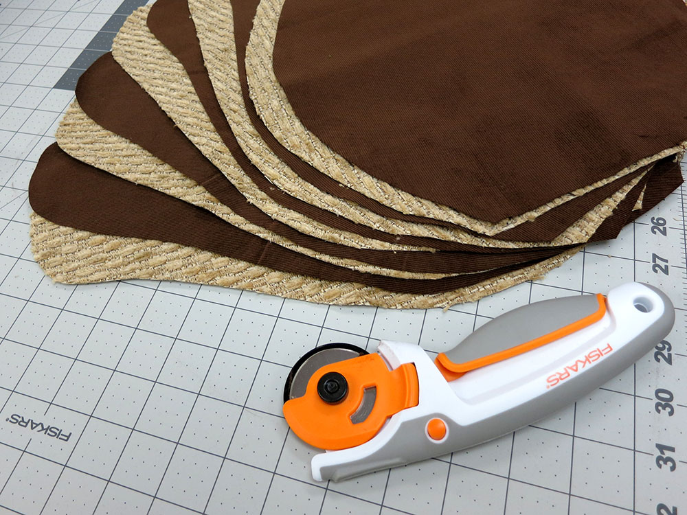 I cut out all 10 pieces and sewed them together. Weirdly the petals made wonderful looking ears. If I’d been working on some other costume that needed big donkey ears, I’d have been all set! Then I stitched the 5 petals together in an overlapping 5-sided ring, with the dark brown liner parts visible at each seam to add detail. Then I started looking at attaching this to one of the backpacks I’d purchased. I decided that I really didn’t want to do that. It was just too ugly to have those straps over his shoulders. So I instead sewed on a pentagonal base using my dark liner material.

 During his day at school, Simon ripped the crotch out of his pants, but I was able to sew them back together for trick or treating. A seven year old can really do a number on slightly tight pants. I guess I should have used some sort of stronger double seam for the crotch, but I don’t really know what kind is best, and I hadn’t had problems there in previous years. That lightweight flannel just wasn’t super strong.


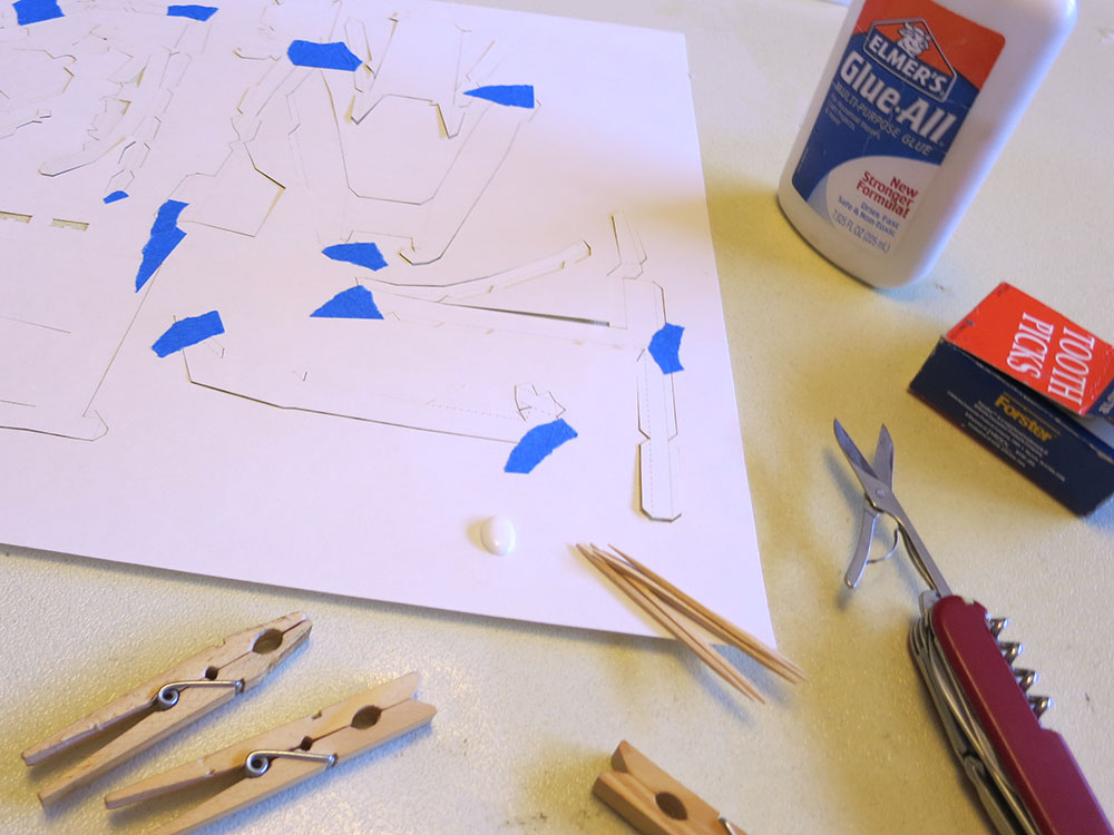
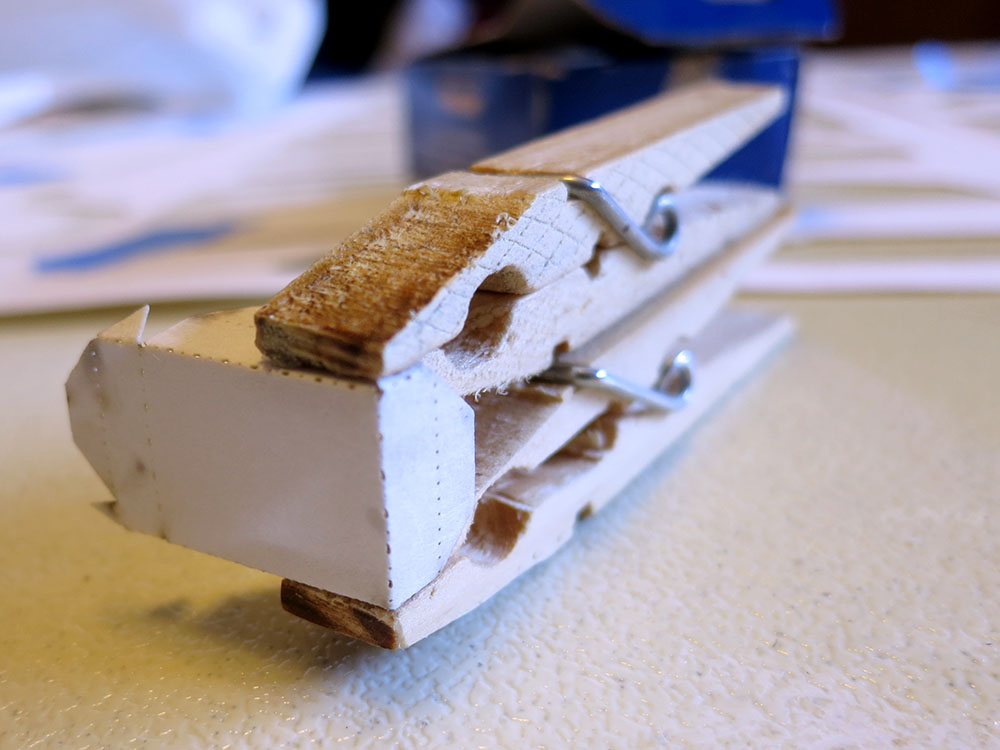

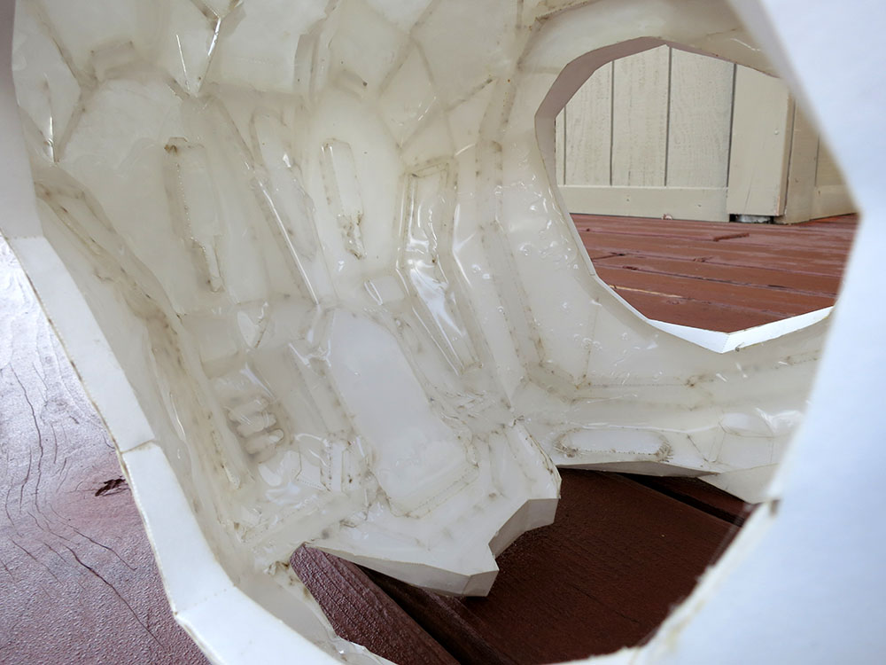
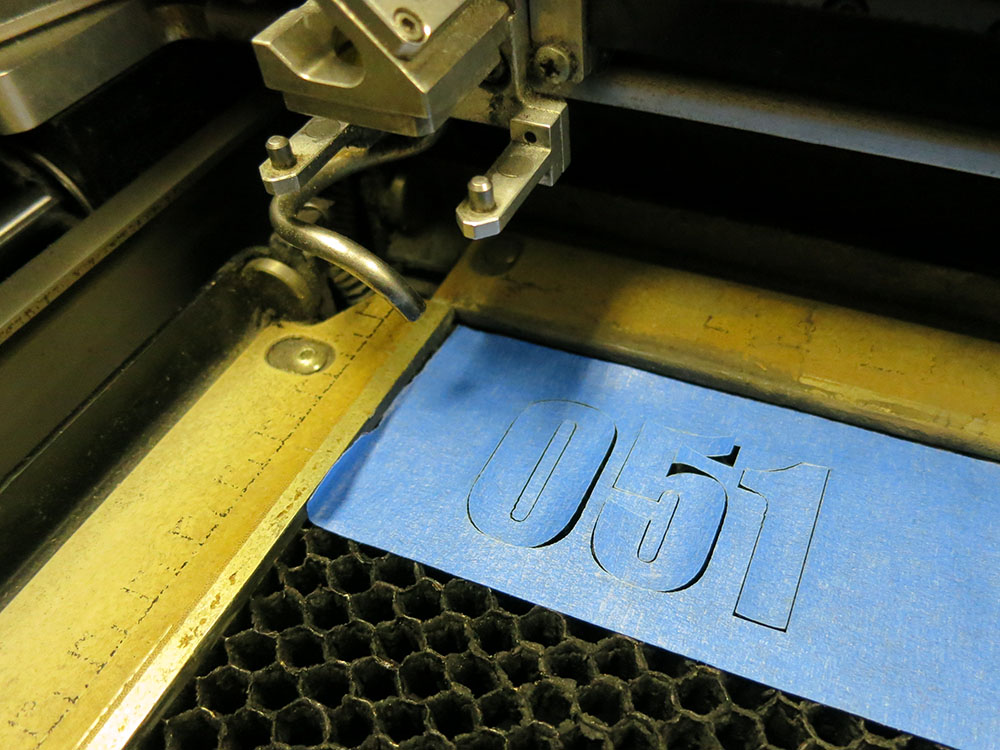
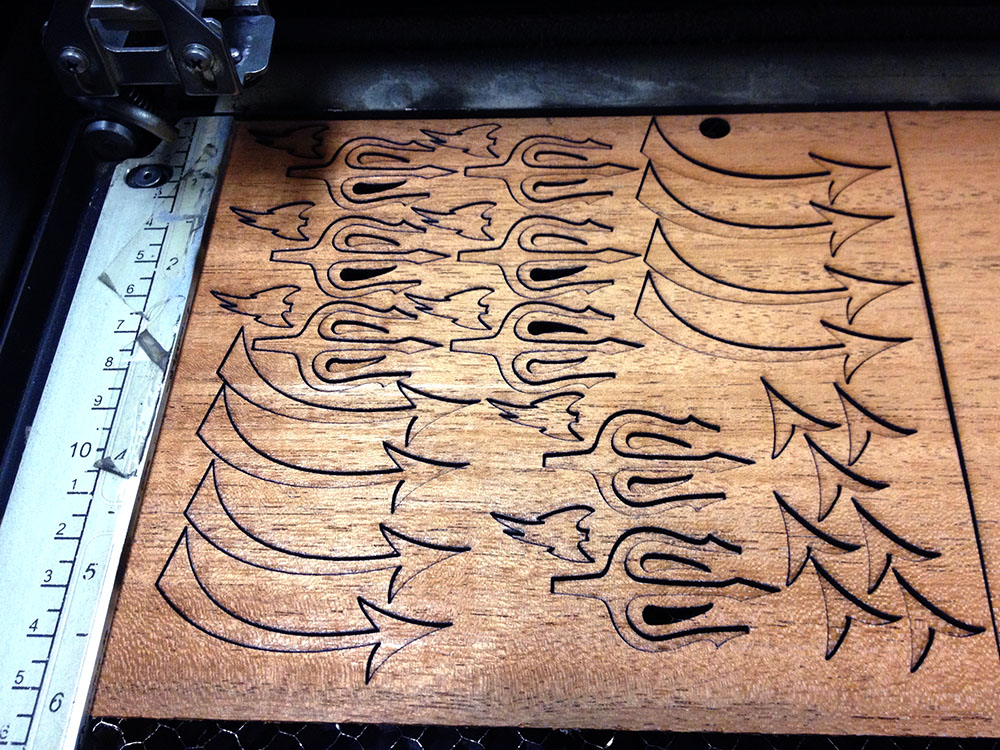
 The laser cutting took about 2 minutes for cut lines and 6 minutes for the dotted lines. The cutter is stupid about the short segments in those perforated lines, so it actually cuts them significantly more slowly than the normal cut lines. Laser time was maybe 10 mins per page, including setup and taping after cutting. The torso was 6 sheets, so it took almost a full hour to cut, but I can only imagine the amount of time saved. How long did the gluing take? I spent a weekend gluing up two biceps and a forearm. I had started a new audio book and listened to it while I was working, so I unintentionally timed my gluing. It took 13 hours 45 minutes for those three pieces. They have about 45 segments each.
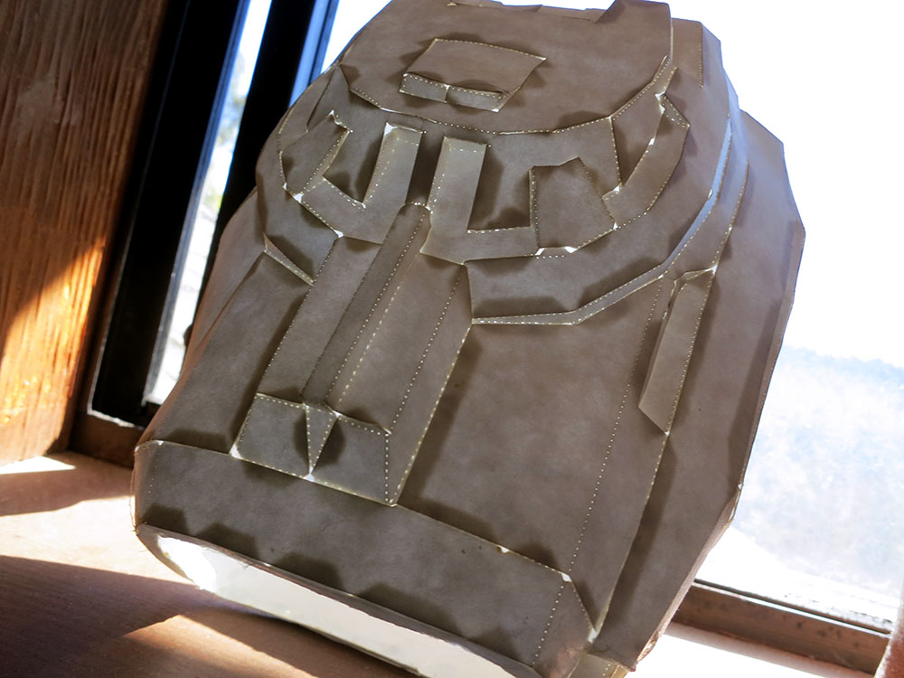
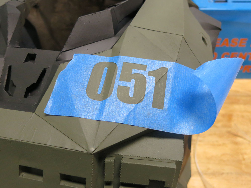
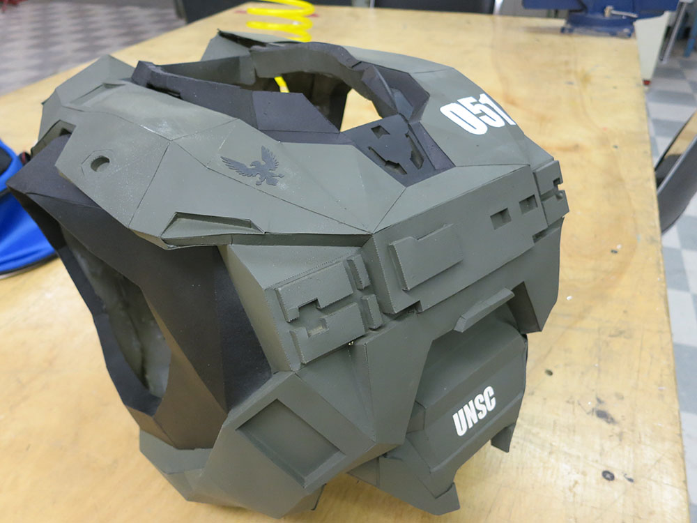
 When I started, I told my son I wasn’t making any leg pieces or the helmet. I didn’t have enough time to build a full suit and the helmet and legs seemed like the pieces he wouldn’t be able to wear for trick-or-treating anyway. Partway though the build, he told me he actually wanted to be not just any Halo Spartan, but the Master Chief. I told him I couldn’t swap armor types at that late date, but I could paint it in the Master Chief color scheme. We were joking that maybe instead of a Master Chief he could go as a Halo Master Chef, and he could have a chef’s hat and apron instead of a helmet and leggings. Pioneer loved the idea, and that’s how the Halo Master Chef project was born. After rejecting ideas like the “Gravity Ladle,” we finally decided that the rolling pin was the funniest of the weapon options.


