
There’s something cool about a mechanical iris. The opening expanding and contracting like magic, the nice radial symmetry. Very fun. Lawrence and I had built the Solar Plotter, and although the output was very nice it has some limitations. Because we were using a large cheap magnifying glass the output lines were pretty fat. I thought it would be cool to have some sort of dynamic line width control, and what would be more steam punk and fun then a magnifying glass with a motorized iris.
The First Build
I started by making a laser cut prototype. I used poster board for the shutters and 1/8″ acrylic sheet for the control rings. The whole thing was pinned together with a few 1/8″ brass pins. The iris worked fine, but there were a few problems. One was that the range of motion for the control levers was not that large, and because it had a sort of snap action it seemed like it would be hard to get fine grain control of the hole’s diameter. Also because there were only 5 shutters the opening was a pentagon, and that might well show up in the final drawing. (If you look closely at the burned wood output of the Solar Plotter you can see little discs stepping along in the ash.) I’d designed it this way to cut down on the number of identical brass sheets I was going to have to eventually hand cut to make the final (longer lasting) shutters.
The Second Build
So I canned that design, and went with a different style of iris. I saw this page about a different iris design. The new design has 12 arc shaped shutters with a pin that sticks out one the bottom at one end and on the top at the other end. I was originally thinking of biting the bullet and snipping these things out of brass sheet, and soldering down short segments of brass rod to act as the pivot and drive pins. As I tried making them it became clear that getting all those parts flat again after all that snipping/soldering was going to be a real pain, and I worried that if the shutters weren’t super flat they’d interfere with each others motion.
All that brass was going to add a lot of weight that I didn’t really want. Of course nothing is more steam punk then a brass motorized iris. But it was time to give up on the complicated hand fabrication of 12 shutters and instead figure out something that I could cut directly on the laser. So I went back to the poster board. The great thing about the new design was that there was very little stress on each of the shutters, so all I really needed was a good way to glue the drive and pivot studs onto the thick paper and I’d be in business. It would have been nice to use very thin plastic sheet for the shutter blades, but I can only cut acrylic on the laser, and that doesn’t seem to come in super thin sheets. (Or at least Tap Plastics doesn’t have it.)
I redesigned the drive plate and bottom pivot plate so they’d accept much larger pins so the pins would have a larger glue area in contact with the paper. I used wooden pins thinking that I trusted Elmer’s Glue and wood bonding much more then some other random glue and acrylic. That was an OK decision, but if I had it all to do again I’d user acrylic pins. All that sanding and champfering of 1/4″ wooden pins was fiddly work and burned more then an hour of time.
The result was a very nice smooth acting iris driven by an RC hobby servo.
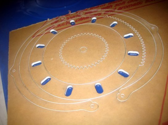
Here you can see the gear that goes on the servo motor (center) the drive ring with it’s distinctive drive slots, and the two arc pieces that make up the back wall of the iris.
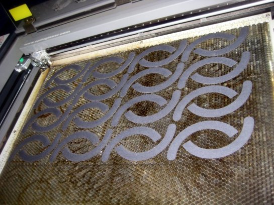
Here you can see all the shutter blades still in the laser cutter. Only 12 are used, but for this kind of thing it’s always a good idea to make extras. The rounded end it the pivot end, and the other end is the driven end.

Here you can see the basic layout of the drive ring. On the right the servo would turn that gear, and the drive ring rotates in the cup of the back wall. Each of the slots drives the end of one shutter blade around. It’s a bit wonky to have this motion without a nice central pivot point but that’s the nature of be beast.

Here you can see the pin around which each of the shutter blades pivots. I’ve just glued all 12 of them. You can see how I had to sand the ends/edges to get rid of any splinters left from cutting them on the band saw. That was a fiddly business and I highly recommend just using laser cut acrylic discs. You’d only have to sand one face, and then use some sort of glue you trust to do a strong acrylic to paper bond. I’m going to do some glue experiments and figure out what works well for this situation.

Here you can see I’ve flipped over the shutter blades and glued more drive pins onto the other end of each one.

Here you can see all the shutter blades in place on the bottom ring. Each overlaps the other around in a ring. Because the shutters go less then half way around the circle there is never a thickness of more then 6 shutter blades at any one point, and the thickness is always very uniform. The hole in the foreground is where the brass pin will eventually pin the semicircular back wall to the base.

Here you can see me taking the iris for a spin. I put the drive ring over all those pins and gave it a twist. The action is very smooth and controlled. The first layer of the back wall is just set (approximately) in place for this photo.
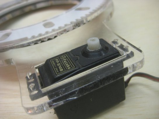
This is an old servo that I had lying around. It has some little screws that will self tap into those holes to hold it in place.

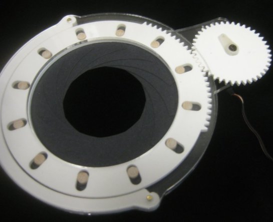
Here’s a bottom view of the iris with the motor in place. When I mounted the motor I realized there was something wrong! The gear didn’t mesh right. I was off by a whopping 0.075″ Crazy talk. I was very worried because I didn’t know where the problem could have crept in. Had I had more stuff selected when I was nudging elements in Illustrator? What else might be wrong? Then I realized what was wrong. I had flipped the design for the bottom plate so that when it cut out the side away from the laser could be the “top” I’d done this because the holes are always smaller at the bottom side (because of the somewhat conical cutting action of the laser) and I wanted the edge that would be contacting the pins to be as close to the base of the pins as possible. However I had forgotten to flip the motor over, and it was now off center. (accounting for some of the extra space.) Phew!
I flipped it back over and we were good to go.
Here’s the final assembly. There’s still a little bit of play (you can see the gap between the drive ring and the back wall) If I end up cutting a new base ring, I’ll bump that motor bracket in an extra 0.04″ and that should be perfect. It runs nice and smooth. But there’s a bit of a problem. The servo rotates more the 180deg. I had designed the mechanism for 180 of rotation plus some modest amount of slop, but on this motor it seems like it might be an extra 15 deg or more. So much for believing something I read on the internet! The problem is that if the motor can forcibly drive the iris past it’s comfort zone (where the wooden drive pins have bumped up against the outside of their slots in the drive ring) the iris might be damaged, and since we don’t know how good the control will be for the servo we have to assume it will frequently be run to it’s limits in both directions. We really should make sure that the iris is OK in those situations.
The easiest solution would be to make the slots a tiny bit longer. Another solution would be to make the drive gear a little bit smaller and scoot it over some. It’s surprisingly difficult to find exact rotation range number for this model of servo. I guess most RC folks don’t care at all.
The original page in the Internet Archive.
