Making the Gandalf Costume


Pioneer wanted to be Gandalf The White for Halloween.  I had made Gandalf’s sword, but I still needed to make his cloak and hat. In the run-up to Halloween, I’d spent most of my time working on Simon’s King Cobra costume, and then I got sick. In the end, I had to design and sew together Pioneer’s Gandalf hat and cloak in 4 hours on Halloween Eve. I couldn’t even work late into the night because I was still recovering. Thankfully, I’d already purchased the fabric to make the costume. So it was strictly an evening of Design & Build. I set up a folding table in the guest bedroom to act as my sewing room so I wouldn’t have to commute over the hill to TechShop. TechShop is awesome for sewing projects because I can spread out on three tables and there’s good lighting and an ironing board and iron. I still use my own sewing machine because that’s what I’m used to. So working upstairs wouldn’t be that much of a step down, and hopefully I wouldn’t have to iron.

Gandalf Costume PatternI decided to go very simple. I only made two paper patterns. One was for half of the arm and another for the back, which doubled as the front sides. Only two pieces of paper! Simple Pimple. Ok, there were also two piece of paper for the hat. The advantage of working at home was I could actually size the thing to Pioneer’s body instead of snagging a shirt/pants and sizing from that.

Gandalf Costume Pinned
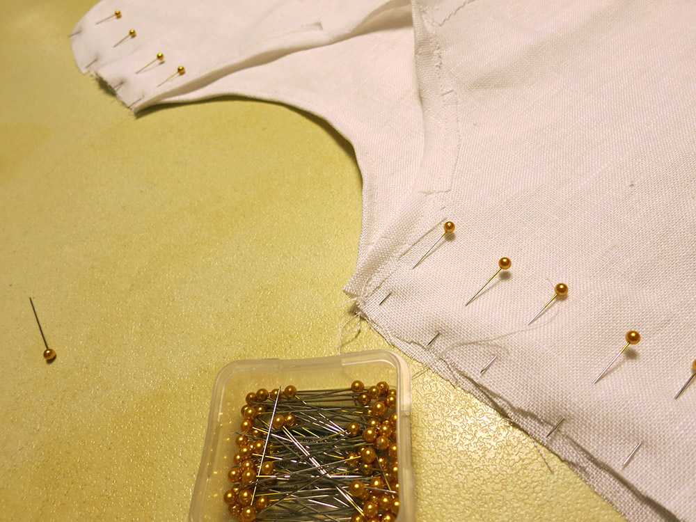
I cut, pinned, sewed, and hemmed like crazy. The only things I put on the cloak above the bare minimum were some belt loops, a sword loop, and an extra layer across the back in the shoulder blades area. I’m not even sure what that’s called on a cloak. I should have double-checked the sword loop height because that ended up being a bit low, and the sword was going to be dragging its tip. Thankfully, the belt loop was big enough to double as the sword loop and the dragging sword crisis was averted.

Gandalf HatI had designed the hat with two intersecting cones of paper. Making the inner cone was trivial, but attaching the brim cone piece at just the right position so it wouldn’t kink the inner cone ended up taking three attempts. This was complicated by the fact that I was also pinning in a hat band, so the actual pinning was stupidly time consuming. Finally I got it just right. Before I sewed the hat together, I took one last look and realized that I had pinned the inner cone in inside out! Horror! I was going to have to pin it again, or the seam allowance would be on the outside of the hat. Not …. enough ….. time. I made an executive decision. I sewed it up the way it was, trimmed the seam allowance very close to the seam, re-inverted the hat and did another seam. That way it looked nice both on the inside and the outside, and the only evidence of my mistake was a little bit of cloth sticking out in the hat band area. Later someone told me this was called a “French Seam.” Funny that I made that up as a time-saving measure.  I really should take some kind of sewing class.

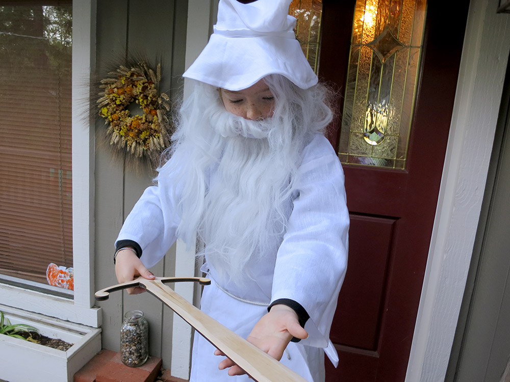
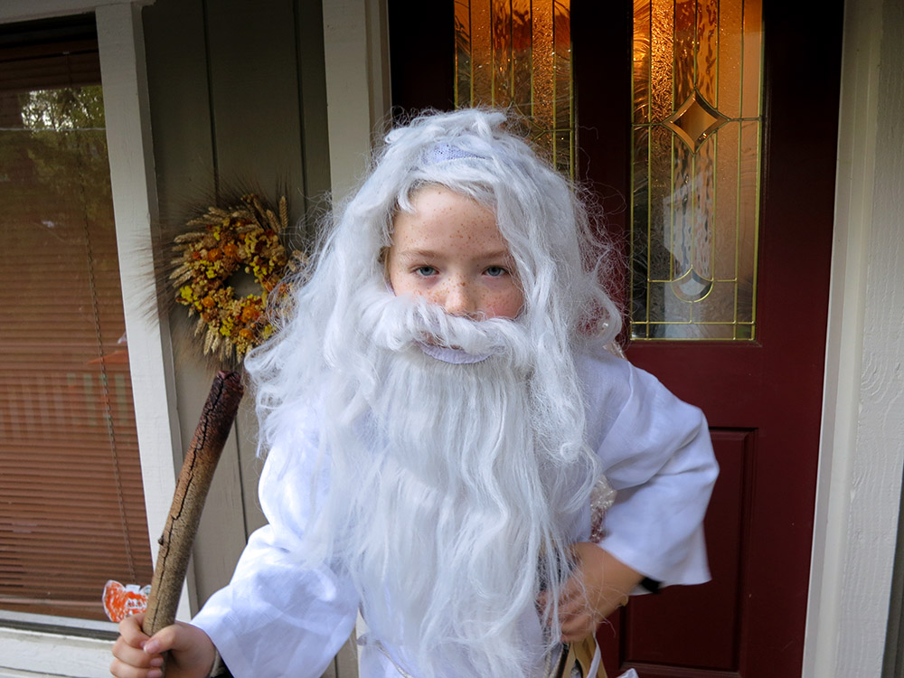
Pioneer looked good in his costume.  Perhaps the hat could have been a bit bigger and stiffer, and the sword loop should have been higher, but basically it came out fine.  Mission accomplished.

PioneerAsGandalf  gandalfDrawsHisSword

GandalfShowsOffGlamdring  GandalfNoHat

Pioneer insisted that I take a photo of him falling into the pit with the Balrog.   Here is the photo after massive amounts of photoshop fiddling to make it really look like he is falling.   Maybe I should have tried a bit harder…  I also avoided mentioning that Gandalf the Gray was the one who actually said “You cannot pass!”  It’s best not to contradict the  wielder of the flame of Anor.

GandalfFallingIntoThePit

Building a Motorized Camera Slide from a Dead Inkjet Printer

PhotoJoJo sent me an ad for a small camera slide.  It was kind of a lot of money, and wasn’t even motorized.   I’ve been taking videos of projects and thought that a little motorized camera slide might be a nice way to spice up those kinds of videos.  I  remembered we still had a dead inkjet printer left over from the kids’ “Take  Stuff Apart Day” that we’d done a few months ago.  Inkjets have a linear motion slide inside.  I thought, “Wouldn’t it be cool if you could make a camera slide with basically just the parts from a printer?”

Motor ControllerI didn’t want to have complex control software, and I wanted it to be mostly made from the printer. In the end, I spent about 4 evenings hacking up something.   There are lots of cheap motor controllers out there, so I squashed my initial instinct to hack up a speed controller out of bits from my junk drawer.  I instead decided to act like an adult and order one of these.   With free amazon prime shipping I could have it in two days for under $10.  I’d probably end up spending more on perfboard and components building a  home-brew driver. Plus, if this project was  a bust, there would be plenty of other uses for the driver board since it could drive a much bigger motor than the one in the printer.


Micro SwitchesI scrounged up some micro-switches and a wall wart to power the rig.  I also ended up buying a switch and a project box from RadioShack.  So the total bill for this project was about $20.  I even (mostly) used wire that was taken from the printer.  I really wanted this project to be simple to do in the hopes that other folks could build one.   The interface was fun to design because it’s entirely electro-mechanical except for the speed controller.

Schematic It was fun to design an interface that didn’t have any software but was still nice to use.  I had a direction switch that you could push in the direction you wanted the slide to move, a launch button that would start the stage moving, and two end-of-travel microswitches.  It was fairly complex behavior from a minimal amount of wiring. I was really satisfied with how that turned out.


End Of Travel SwitchI laser-cut some mounts for the end-of-travel switches so they could be mounted right on the rod that the carriage travels along.  The mounts allow the switches to slide along the rod to position where the camera motion should stop.

Probably the single most time-consuming thing was hacking down the carriage.  I used a cutting disc on my mototool to hack the carriage down to a roughly flat area and then used some Bondo/black spray paint to make it look like a nice, flat surface.  I also stuck a short 1/4-20 screw up though the center to mount the camera on.

I was planning on mounting my Cannon S100 to the slide.  It’s light, so the whole rig didn’t have to be super strong.  Luckily, I happened to have a ball-and-socket camera mount sitting around from an old project, so I hooked that up to the screw on the carriage.

Camera Slide Top View  Camera Slide Bottom View

At this point I realized that for a camera slide this small, most of the usable camera motion is VERY slow motion, and the printer’s motor was just not up to the task when running open loop.  If I salvaged the position encoder and hooked up an Arduino as a controller, I probably could have managed to get very nice motion of of the rig, but since the goal was a one-evening super easy/cheap hack, it was a fail.  Putting a gear-head motor in there would also have worked, but also violated the cheap and easy premise of the build.  Here’s a video of the final result.

cameraSlideDone

I wouldn’t be surprised if there’s another camera slider project in my future.  This time with more motors and software.   This was a great learning experience, and as the Lego Guy said, it’s time to “Keep Tinkering!”

Making an iPhone Microscope

Microscope Parts After CuttingThe other day someone sent me a link to an instructable about using your smart phone as a microscope.  It uses a laser pointer lens, and I knew I had one of those laser pointers at home in the junk drawer.  Its batteries were dead, and its lens could be repurposed.  I had plenty of scrap acrylic around, and I quickly illustratored up the parts for the microscope.

I have an iPhone 4s. I looked up the camera geometry and position of the lens because I wanted to make it super easy to flop my camera down and take some macro photos.  The instructable uses wing nuts, but I thought it would be nicer to have large straight knurled dials to move the focusing stage up and down. I cut out a few dials that would go around the 1/4-20 nuts.

Gluing On The LatheI used JB-Quick to glue the nuts in, and I glued them using the lathe to ensure that the discs were fairly plumb with the bolt.  After gluing, I peeled off the blue protective plastic. I wanted to make sure the specimen slide would be able to ride smoothly on the two nuts.

Microscope Stage Focus NutsThat was pretty much it in terms of assembly trickiness; the rest is just bolted together.  I originally had cut out some acrylic discs to put around the carriage bolt heads, but I decided it looked nicer to leave those out.  I guess you could just put some stick-on rubber feet on the bolt heads if you were really worried about scratching up the table.

I did  a couple of test cuts to get the exact diameter hole needed to hold the lens.  The slightly cone-shaped laser-cut hole is perfect for pushing a lens down into.  I have three pieces of plastic that align the camera.  Right now they’re just bolted on. I guess if I wanted to I could make sure everything was in a really good position and then put a drip of solvent to glue the guides down.  So far I haven’t bothered.

Microscope Assembly Begins  Lens Assembly Close Up

Then it was time to try it out!  First I tried looking at a strip of pins.  Not really very exiting. What else could I look at?   I remembered earlier that day I’d seen the husk of a great big Jerusalem cricket in the the corner of the garage.  I went and snagged it and had a look.

iPhone Taking A Picture  MicroScope With Bug

iPhone On MicroscopeThe rig worked reasonably well.   Lens alignment was quite good, and the stage was easy to slide up and down with the nuts.  The bolts don’t make the best sliding surface, so moving the slide up is smooth, but sending it back down is a “spin the nuts down and then manually press the stage down” affair.  Not optimal, but I was worried about making those stage holes too big and having problems with the stage moving around laterally, which would be worse for trying to do focus stacking.  Frankly, I like the non-focus-stacked images a bit better, but with some practice I might get better results.

Bug Leg Closeup  bugFootWithFocusStacking

Is that a photo of delicious king crab?  No.  That’s a bug’s ankle.  That first photo is just a photo.  In the second one, I took a number of photos moving the stage up a little between photos.  You can touch and hold your finger on the iPhone to lock focus and exposure so you can do this without the phone screwing things up.  Then I imported all the photos into Photoshop, and I had it take a stab at merging the layers using the most detailed areas of each photo.

Bug Thorax Focus StackHere you can see a much deeper photo of the thorax.  I have yet to get super great results with the stacking. Photoshop often screws up the alignment of the photos, and I have to turn off some of the layers.  You can see some banding of sharp and blurry near the edges of the photo.   Those were formed by layers that Photoshop failed to align, and I had to just turn those off.  Sorry the photos are kind of gross.  That bug was just the most interesting thing I happened to have on hand.

I also fished a quarter out of my pocket.   I thought about trying to make a giant panorama of the quarter since it’s kind of flat and didn’t need any focus stacking tricks, but the shiny metal surface is very reflective and viewpoint-dependent, so it probably wouldn’t stitch together very well.   There’s also a photo of a blown halogen bulb filament.

quarter  brokenFillement

Here’s the final illustrator file.  You’ll have to do the kerf compensation for your laser.  Also you’ll have to adjust the lens hole to fit your lens.   I cut a series of holes in the scrap parts of the 1/8″ sheet until I got a good match.  Remember this design sized for an iPhone 4.  I used 4″ carriage bolts just like in the instructable.  If you make one of these, send me a picture!

Making Glamdring The Foe Hammer

Sword SketchPioneer wanted to be Gandalf the White for Halloween this year.   Personally, I wouldn’t have chosen white for a costume that was sure to be grubby three minutes after it was put on, but Gandalf the White still had a long and difficult journey ahead of him  so a few wrinkles and stains would fit right in.   Pioneer had already selected a staff, but I wanted to try laser-cutting his sword.  I’d been working hard finishing the iPad version of our app, so I was getting started on Halloween a bit late.   The sword seemed like any easy first piece, so I snagged some plywood and a scrap piece of wooden molding and went to work.   I got out the bag of leather scraps that I’d gotten from a coworker in trade for one of my wooden puppy dogs.  I figured maybe I could cut a leather spiral or strips to form the grip on the hilt of the sword.

I had reserved the latest possible slot on the laser from 10:30pm to 11:30pm, and my plan was to design the sword in the time between getting out of work and the start of my laser time.  We’d been getting the final cut of our iPad app ready to send to Apple, and I ended up working until 7, but finally I shifted gears and started frantic work on the sword.  I did a quick sketch that I liked, and I started designing the sword in Illustrator.  I noticed that the leather scraps I had were all pretty small, so a big spiral of leather wasn’t going to be possible. I decided instead to cut out a lot of oval leather pieces and stack them to form the handle.

The laser bed is 24″x18″, so I had the choice of making a really stubby sword or doing something tricky.  I decided to cut the blade of the sword on the diagonal in the machine for maximum length, and then make the handle/blade guard out of another piece.   I had some really thin pieces of wood that I sandwiched on either side of the joint to give it strength, and add the runes for Glamdring to the sword.   This was going to be a one-night build, so I had to abandon any ideas of making the sword glow, etc.

Laser Cut Sword PiecesThe big problem with putting material in the laser on the diagonal is alignment.   I cut the outline of my piece of wood molding out of a scrap of cardboard, and used that as an alignment jig.  It worked fine for the basic cutting, but when I had to flip the wood over and etch the central fuller on the other side of the blade, the blade was off by a few degrees and the detail was clearly not super centered.   If I had it to do again, I’d have the blade oriented the other way around so being off by a few degrees would hardly be noticeable.

I used shape interpolation in illustrator to make the 35 pieces I wanted to cut out of the leather.   It was  fiddly and time consuming to position the pieces on my various leather scraps.   I used a pencil to number the pieces so I could stack them from large to small without mixing them up.   Then I cut the parts for the hilt out of my piece of plywood.  In the half hour between the end of my laser slot and TechShop’s midnight closing time, I went and used the big belt sander  to sand some profiles onto the blade.  Kind of a freehand grid to shape.  I didn’t want the thing to actually be sharp, but it gave the blade a more realistic shape, and kept it from just being a flat cutout.

Then I went home and glued it up.  I wanted to be able to let the glue set up over night.

Glamdring Runes and HiltswordWithNoHilt

As I was assembling the blade, I realized that I liked the look of it much better without the piece that had the runes on it.   Leaving it out makes the blade to hilt connection a lot weaker, but I just liked the look of the blade without that stuff on there. Also, the little cutouts on the ends of the cross guard looked kind of cheesy, so I just left the rune piece out entirely.  The sword hasn’t broken yet, so I guess it was the right call.

Stacking the Leather to make the hilt I woke up early the next morning and glued the 35 leather pieces together to make the hilt.  Because I was using leather scrap of different thicknesses, not all of the pieces had been cut out cleanly by the laser, so I had to tear some of them free.  They slid onto the hilt, and the locking mechanism I designed into the butt of the hilt clamped the discs in nicely. I probably didn’t even need the glue.  One problem with the leather pieces I had torn free had a lot of wispy strands at the edges.  This made the handle rather shaggy.  What to do?   I knew that trimming them would be a pain, so I simply assembled them as is, and used a propane torch to burn the little strands off when I was  done.

Sword Handle Leather DiscsIt worked great!  The strands would get hot and burn off long before the surface itself got hot enough to burn, and it was super fast.   I’ll have to remember that trick!  You can see the crescent-shaped piece that locks all the discs into place.   I had some laser-cut flats that could be clued over that.

Sword On LatheHaving such a flat element at the end of the hilt seems kind of sad though, so I quickly turned a piece of wood, cut it in half on the band saw, and glued it in place covering that area.   I put ridges on it to kind of echo the leather discs, but in retrospect it would have been nicer to use a smooth piece since the other lines of the blade/tang/cross guard are very clean.

Finished Sword HiltI think the final sword came out nice.  Gandalf  certainly was happy with it.swordInPlanter  swordHiltCloseUp