When I was young we used to spend time at my Grandparent’s house. It was a farm house with a porch swing and there were lots of fun things to do. My Grandfather would tell the story of my first trip around the yard on the go-cart. I was very young and when I came back around I told him I’d “never operated a motor vehicle before!” and he thought that was hilarious coming from such a little kid. There was a mini bike (until we broke the front fork doing jumps) we played Jarts, yes all sorts of “dangerous” distractions.
One of the fun things we’d do is play an old wooden Labyrinth Game that they had. We played it so much that we could run the ball all the way though and all the way back. We played it so much that we tried playing it with our feet. One day one of the control strings broke and although Grandpa “fixed” it he wrapped the string around the wrong way. Reversing that control, and permanently invalidating all our muscle memory for that game.
The Idea
Though TechShop I have access to a laser cutter. Each year I build some sort of crazy Christmas Project, and this year I decided that a Labyrinth Game would be an awesome thing to make with the laser. I decided on a Egyptian with a retro-technology flavor. (To fit in with the Secret Society theme I’d been following for a few years.) I went with the kiddo’s to the local Rosicrucian Museum to do some first hand research. I went to Toys R Us to see if they had one of those games. I talked to 4 people there and non of them had any idea what I was talking about. I then went to a smaller local toy store and the guy knew at once what I was talking about, and he had them in stock. This more modern instance of the labyrinth had the same design (same hole pattern/course) but had been cheapened in a number of ways. The metal balls were smaller, but the course had not been fully adjusted for that size change, which made some shortcuts/cheats possible. I was able to finish the maze on the third try though, so my muscle memory from 25 years ago seemed good. It was only $21, so you can’t expect much at that price point.
The Design
I started in on the design, I wanted to make a lid for the maze so it would come as a decorative wooden box. I was originally going to put brass clasps on the lid, but eventually had to abandon that plan because of time constraints. It would both cost a lot and I’d have to strip/age the brass fittings, and I was planning to build 6 of these things so it was better to keep it simple. I did some sketches, and looked at Egyptian Art. I noticed that the Scarab was a nice fit thematically since he’s such a famous ball roller. (Although this project didn’t involve any dung.)
I had bought a lot of very thin wood from Minton’s in Mountain View when they went out of business, so I decided to do an inlaid wood Winged Scarab on the box lid.
Normally with these projects I do 4 of them by Christmas Day, but then have 2 others I finish up before New Years. (For out of town folks where the timing isn’t as critical.) However when I started working on this one I realized that the physical size of the project was going to require more laser time then I was used to using. It takes a full hour to etch the scarab on the lid. So I quickly realized I wasn’t going to be able to schedule enough laser time before Christmas to cut/etch all the parts needed for all 6, so for the first time I limited much of my part cutting to the basics I’d need for the first 3 and then I’d cut the rest after Christmas when laser time is a lot easier to schedule.
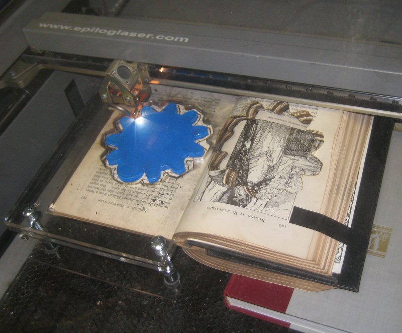
 The 60watt laser deep etching the scarab into the lid.
 The laser etched ball glued into the lid
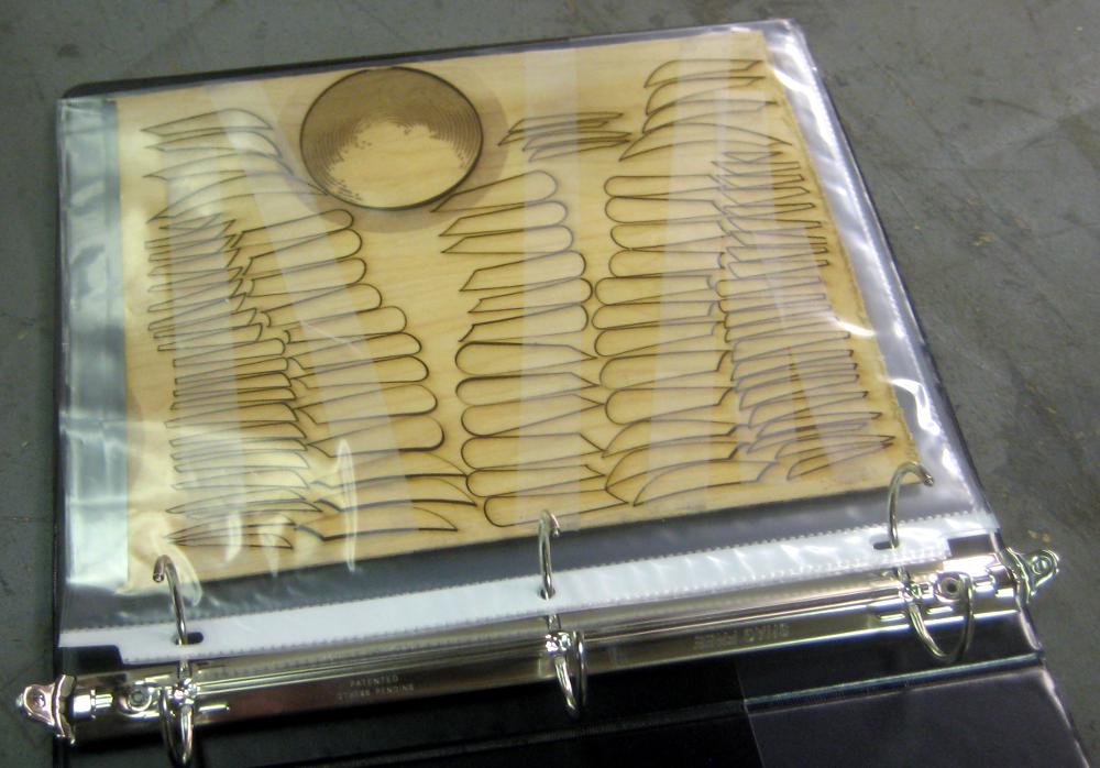 This is how I organized the parts. They are laser cut, but I tape them down to the surrounding wood before I take them out of the laser. That way the uncut material acts as the parts organizer, then I can just slip them into these three ring binder page protectors. Using this system one three ring binder can keep track of all 8 zillion parts. As long as you never EVER pick up the binder upside down and dump everything out! I put a big orange arrow on the front of my binder to help keep that from happening.
 The main body being glued.
 There are 88 pieces for the wing segments alone, so it takes a while to glue up. After the parts go in I clamp them down to dry. The pieces aren’t a super tight fit, so hopefully that’ll leave enough room for expansion/contraction of the wood.
 It is ready to clamp, but I didn’t clamp this first one. It’s always a learning experience, so this one was never fully flat/level. Later ones were better in that regard. I had 3 mistakes in the wing segments. (two parts were swapped, and two were actually the wrong shape) So I had to figure that out, and cut extras. Once all that was ironed out things went more smoothly.
 A shot of the very first prototype in normal plywood, and two of the final ones in the 1/4″ Mahogany Ply that I got for the project.
 The lid after being glued to the sides and with it’s first coat of Linseed Oil.
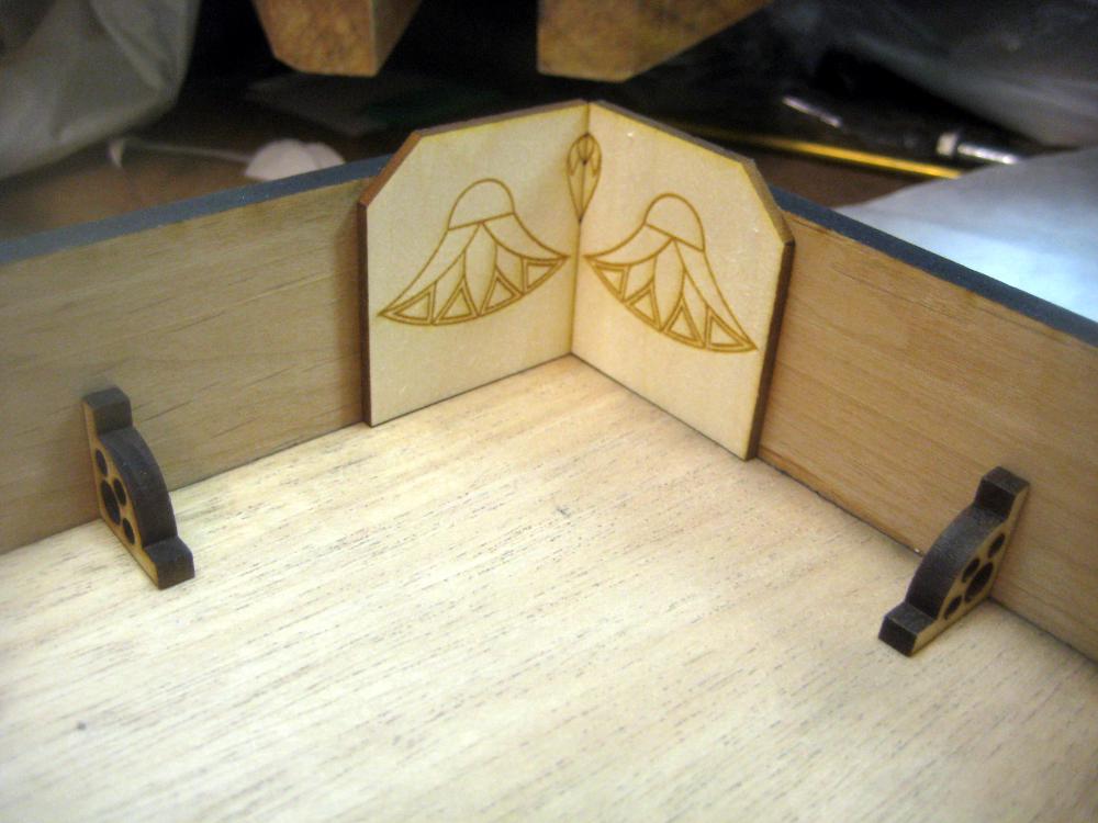 The inside of the lid before finishing. I wasn’t too happy with these two corners. They align the lid to the base, but don’t look that great. Later I tried a bit fancier shape/look. the little right angle brackets with the holes are nice and fancy looking, and quite simple to do. Of course that’s 8 more things you have to glue in (two on each side of the lid.)
 The lid sitting on one of the sides just to show how the wings will work. this is before I started the Linseed Oil finish work.
 This is one of the sides laid out with one of the knobs. Above you can see the zip lock bags I used to organize thick knob segments. I made the knobs from three segments of 1/4″ wood plus a very thin wood layer for the eye.
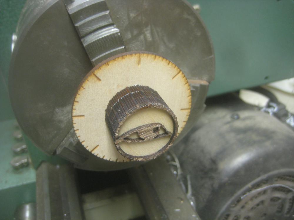
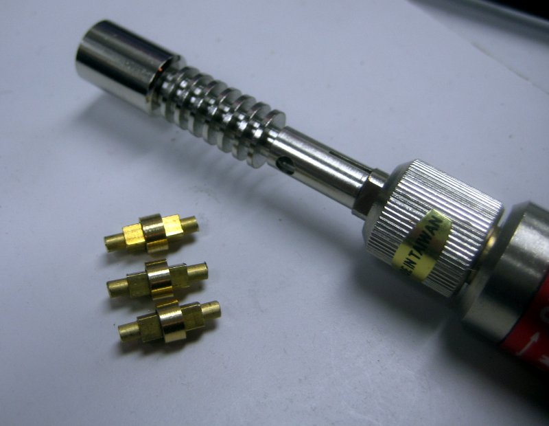
 The knob is made up of 4 parts. You can kind of see the funky strait knurl.
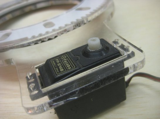
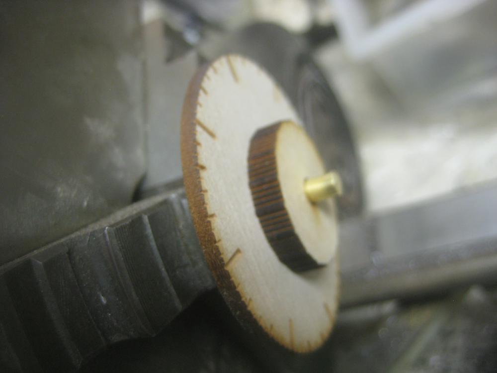 I glued the knobs up on a brass rod held in the lathe’s chuck, so you can make sure the rod would be plumb. Otherwise the stack of laser cut parts is bound to wobble as it turns. However you could just as easily do this with a piece of brass rod stuck into a hold that was drilled plumb. There’s no real need for a lath with this project. It was there, and that made it easy.
 You can see a little to much glue sticking out of one of the glue joints. It’s nice to wipe it down with a damp sponge to reduce the amount of glue visible.
 Here’s an early test cut of the corner joint. The laser cuts in a slight V shape, but you can compensate for that a bit by shaping the fingers into actual dove tails. (Thanks Heath for the idea!) However you can only do that in one direction if you try to compensate in two directions you get a tight joint that needs a teleporter to be able to assemble it (since there are then wide fingers on the outside of each joint) I guess you could do it the other way around, and have 2 axis fixes for both joints with reverse dove tails, but then I would have had to flip the wood over after etching but before cutting, which would have been an alignment hassle. The joints where plenty tight as it was. This test is using Cedar, but I ended up using Alder which has a less pronounced V shape to the laser cut. (And which I could get locally at Home Depot)
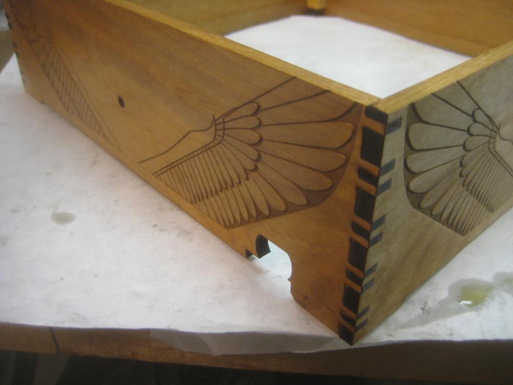 Here’s a final corner with a detailed look at the ball exit. The bottom part of the box extends to create the ball return area. That makes it much stronger since there’s 1/4″ plywood supporting the return area instead of something just glued onto the side.
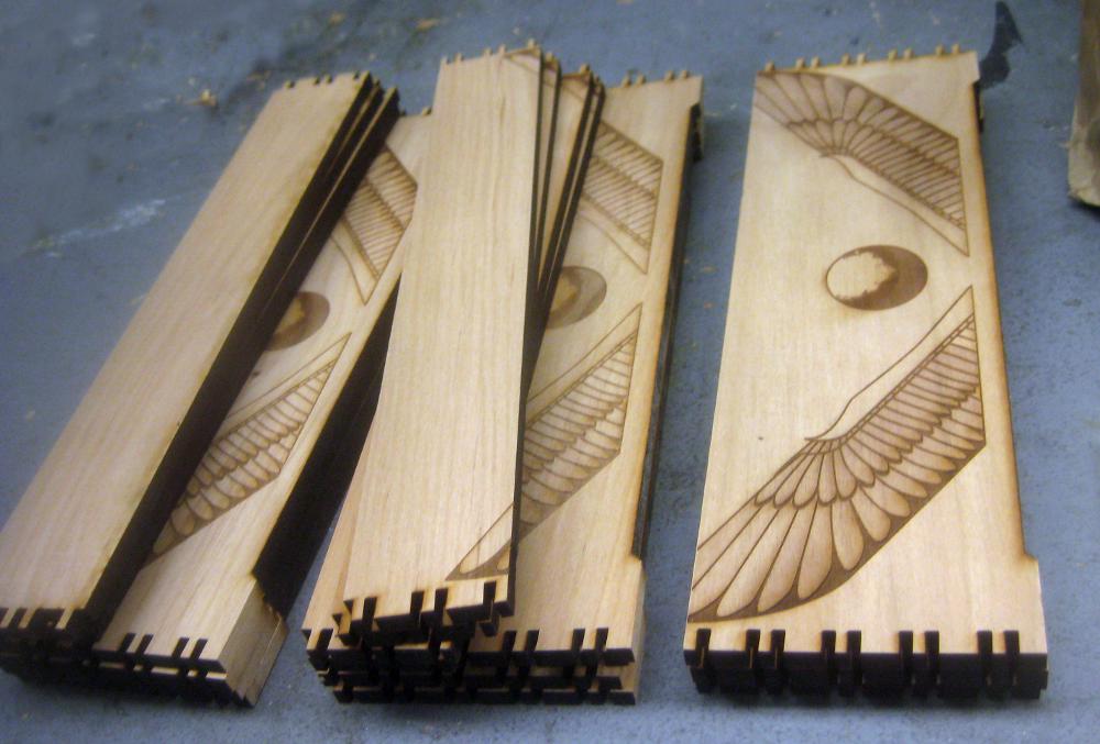 After the design was done I had to crank up for mass production. Here are the sides/lid sides for three boxes (well minus the lid sides for one.) A set of 2 sides takes about 15 mins to etch/cut out on the 60Watt laser.
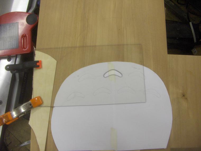
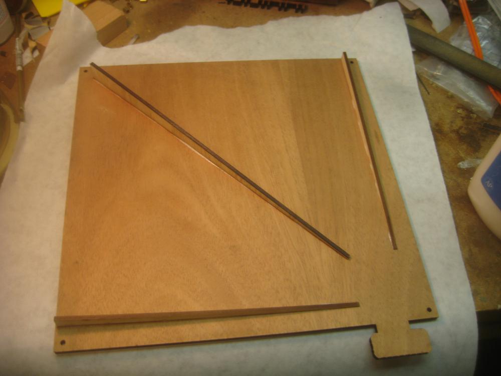 Here’s the design of the box floor. It has 3 wedges which will hold the tilted floor that makes the ball go to the exit. You can also see the 4 screw holes since the floor needs to be removable for possible maintenance.
 I sanded the bottom corner of the tile floor so that it can smoothly go down to almost nothing at the exit port.
 I do however have to provide a special corner piece to keep balls from getting stuck behind the post that the screws screw into. In theory the ball could still fall onto the upper corner of this piece and get stuck, so if you really cared you could sand the top to be slightly curved, but the chance of that happening are small enough that I just don’t care to do the extra hand work to handle that case.
 Here you can see three of those corner pieces getting glued down. The middle tilted floor was the very first floor, using different wood. On some of them I also sanded a slight dip in the top of the plywood at the exit, but that turned out not to be necessary and it doesn’t look that great.
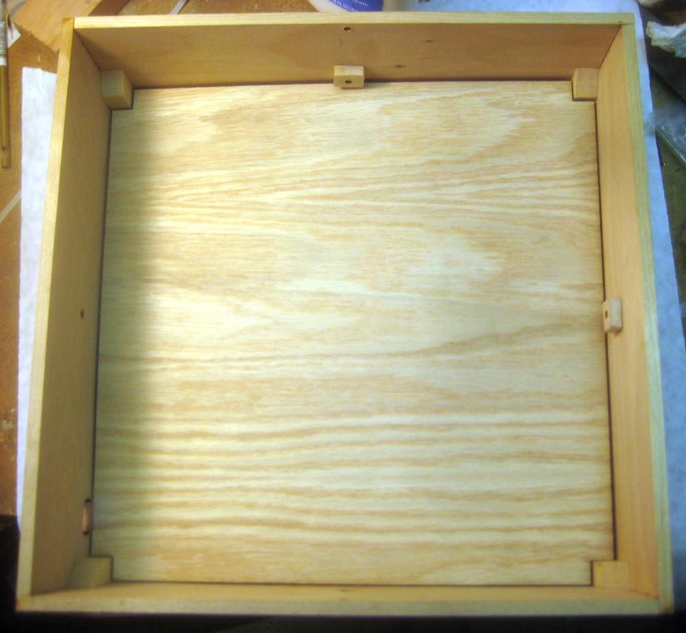 Here you can see the tilted floor in place. You’ll notice that the blocks glued into each corner (so the base can screw into those blocks) have tops that are cut at an angle to make it so the ball can’t get stuck on top of one of the corner blocks. You’ll notice that in this fit up I don’t have the special corner piece glued in yet.
 I decided to wind my own springs for this project. Mostly because I couldn’t find the right quantity of the right size/tension of spring locally. This wasn’t that hard to do, but was a bit of a time sink. Here you can see me using a Jorgenson clamp to tension the wire as I hand crank the lathe to wind the wire into this brass rod. That is the easy part. The annoying part is then cutting/forming the ends on the wires.
 Here you can see two of the better resultant springs. I used a dull Exacto blade to spread the coils enough to get in and bend the loops the rest of the way out with pliers. After the first three were built I had some time after Christmas and found some suitable springs at Tool Land, so I only had to build the first 6 springs, not all 12.
 I used brass tubing pressed into the wood to form bushing for all the brass rod joints, this makes for super smooth action and long life.
 Here you can see me cutting a bunch of the bushings. I used this super cheep Harbor Freight micro chop saw, and hot glued a stop to the saw at the right distance. That makes it super easy to cut 20 zillion of these things. Note how the stop is angled and only touches the edge of the tube, so it doesn’t cause binding when the tubing cuts through. After you’re done with the stop you can just pry it off of the saw. Some day I’ll make a fancy tubing holding/adjustable stop system, but this works well as long as you don’t have to do too many different sizes, and it could just be used in the saw as-is. I didn’t have to dive into an extra project rat hole.
 Here you can see one of the bushings in place around the rod.
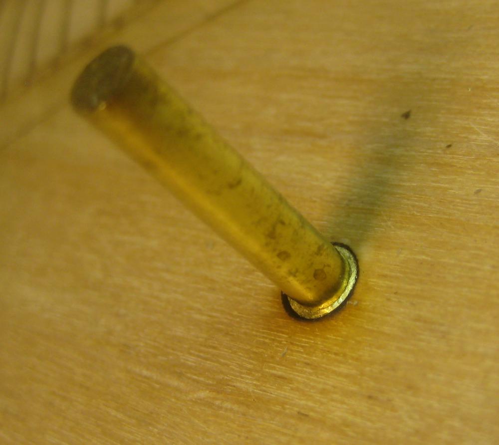
 I also made a number of pivot pins using a round wooden washer and a bit of tubing. You can see one here (blurry) ready to go into the hole.
 Here you can see a frame getting glued to the maze floor. I laser etch the locations of all the wall segments, and put numbers in them so I know which pieces go where. There’s also an arrow, and hazard numbers for the game itself. Notice how I used scraps of wood that were cut from the jaggy edge areas as clamping sections so the clamps wouldn’t damage the pointy parts of the wood. The first one of these I did I didn’t do that, but used padded spring clamps, but there was some slight damage done, so I switched to this system. There are about 45 pieces that get glued down to make the maze.
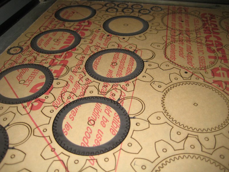
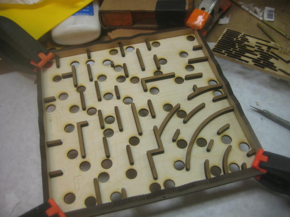 Here is the maze partially populated. I didn’t bother to number unique segments since there aren’t a lot of them and it’s easy to keep them strait. In the upper right you can see the piece of wood that the parts are coming from. The parts are numbered in columns from top to bottom 13 to a column.
 Here’s a closer view including the now fully empty parts sheet.
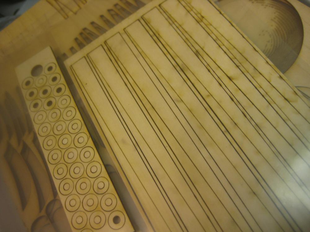
 The walls of the maze have this herring bone texture on them, including miters at the various intersections. The circular arc wall segments have a slightly bigger pattern because it was a pain to get them distributed along the circles in Illustrator. I think I could do a better job now knowing more about pattern brushes, but I was just using the Offset Effect, and getting that with perfect spacing was a pain.
 Some of the miter work on the maze walls. Lots of tiny herring bones.
 Here are some more parts glue drying getting ready for assembly.
 Here you can see how easy it is to make a mess of wooden washers (left) and wedges for the tilt floor (right). This is enough for all 6 labyrinths.
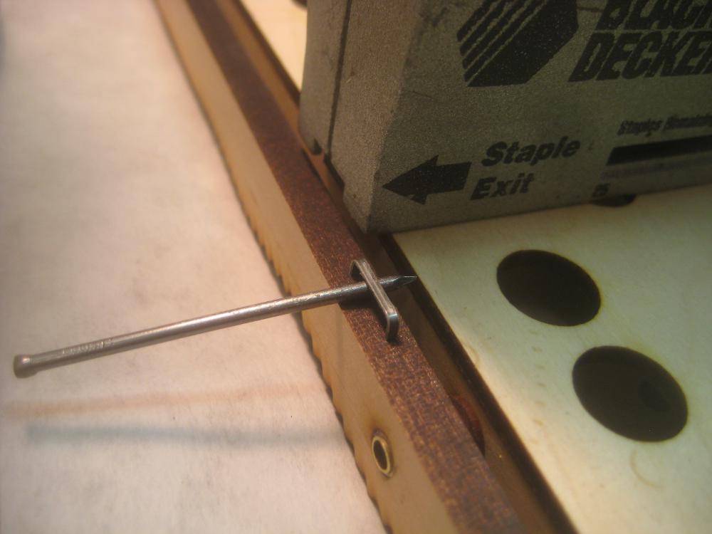 I was originally going to drill/bend brass wire loops to attach the drive train to the pivoting frames, but that was going to take FOR EVER to do, so I opted to just my staple gun. This was terrifying because I was stapling into fully finished things on Christmas Eve. So being off and having a staple come splintering out would be VERY bad. So I practiced on some scrap first. I used this brad to keep the staples from fully seating so you could then tie strings/ attach tensioning springs to the staples.
 Here you can see one of the springs attached.
 And the way that the spring tensions the string as it wraps around the rod.
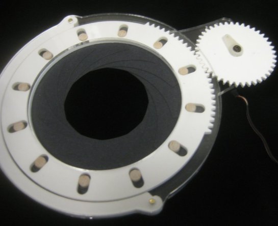
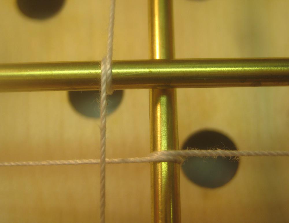 A closeup of the two rods in place with the strings on and tensioned.
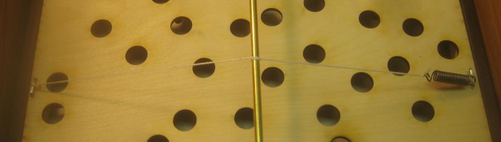
 That’s the full view of both rods in place and strung up.
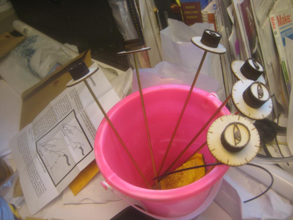 The knobs for the first size mazes are sprouting like strange flowers from a pink bucket. (glue drying stand.)
 My brass control rods are 5/32″. Thankfully they make 5/32 locking collars for some sort of hobby use, so I was able to buy them for cheap. Here are enough locking collars for two mazes.
 A closeup of one of the collars before I put the set screw in.
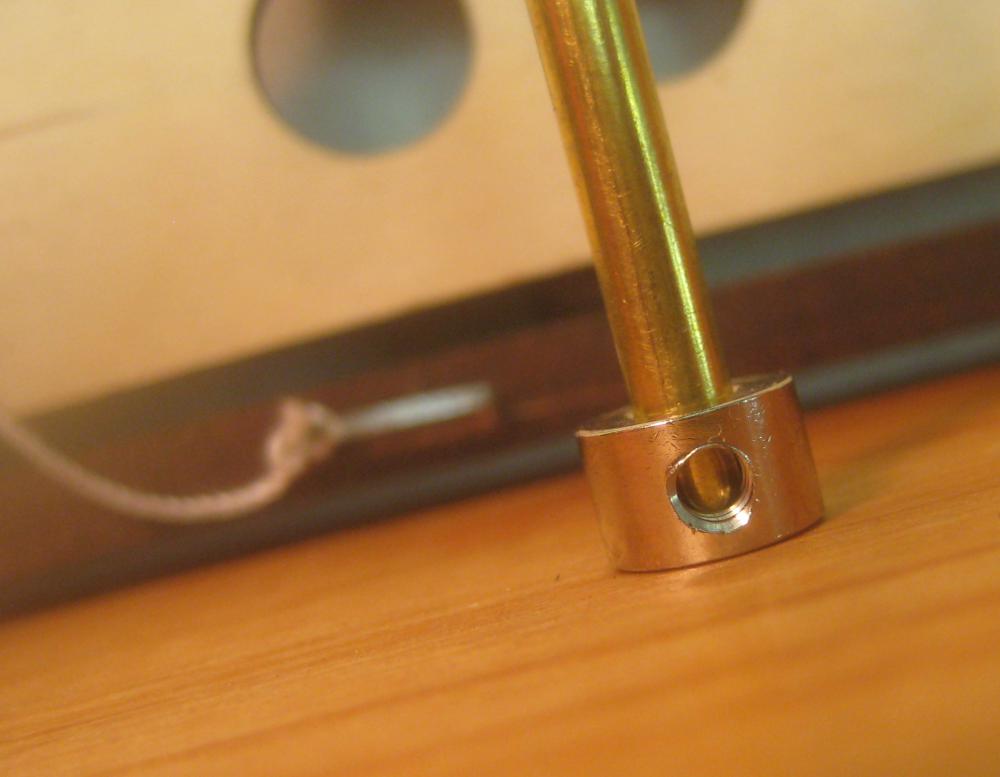
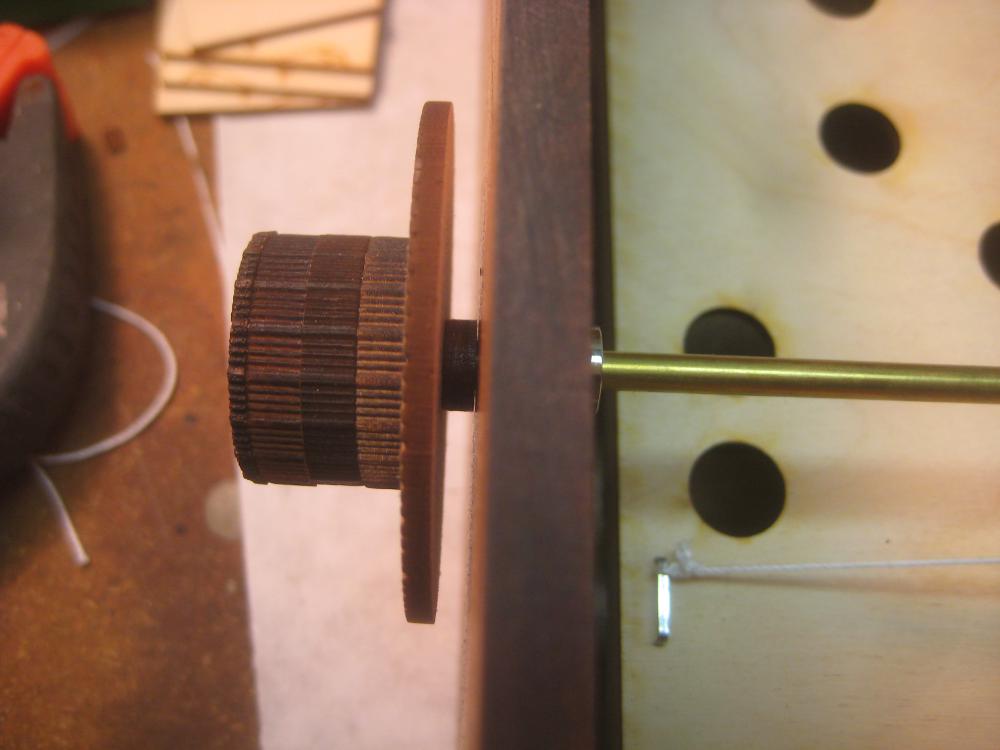 This is a closeup of one of the knobs with it’s spacer washer and locking collar in place.
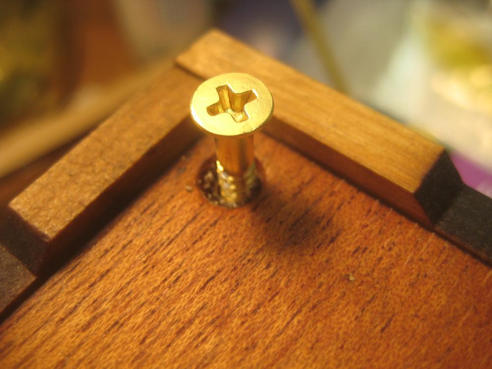 The bottom of the box screws into place just inside the corner feet that that box has.
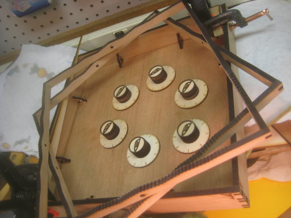
 Both frames and the knobs in place for the first time. Time to play test! The first play testing happened at 9pm Christmas Eve, so it was good that it worked because there wasn’t time to make any major changes. I did end up re-tensioning things to deal with some stretch in the strings/knots.
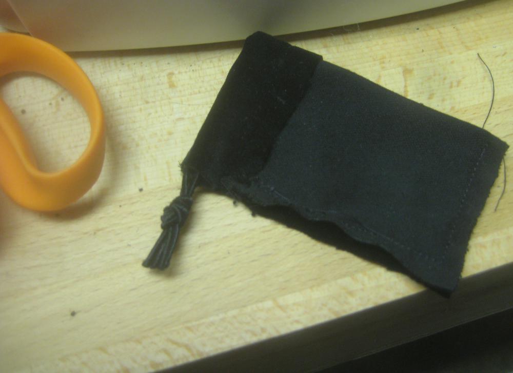 Then it was time to sew up some black velvet bags for the ball bearings to go in.
 There the bag is turned right side out.
 The three balls on the velvet bag.
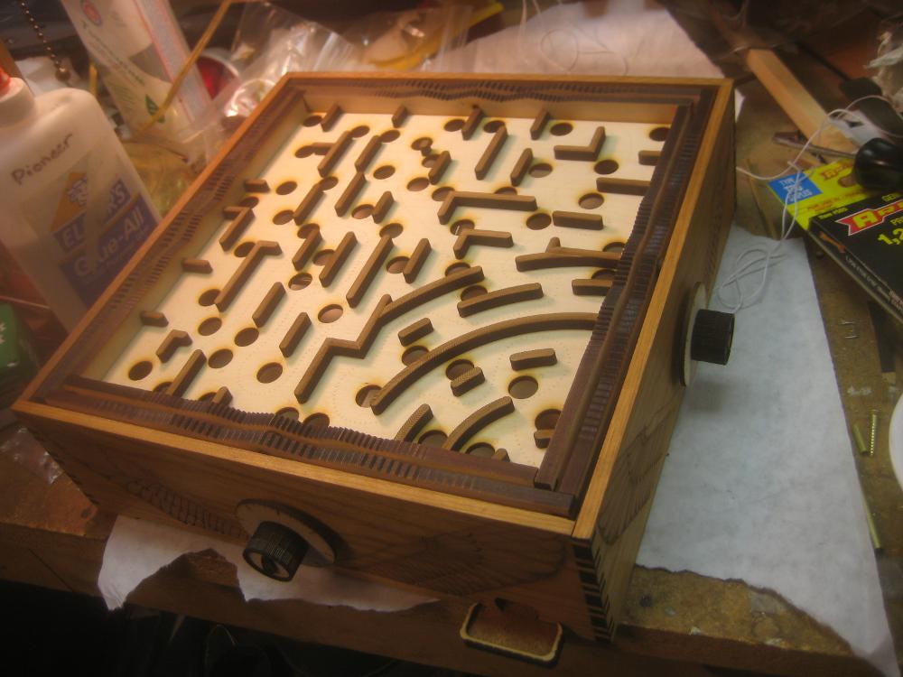
 The maze opened up so you can see the maze surface.
I made a video of the laser cutting, and the kiddo’s playing with it on Christmas Day.
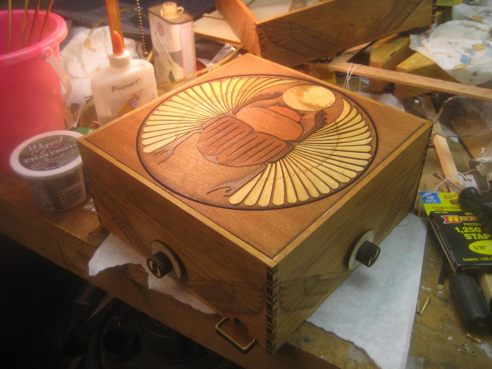
The final finished box. I managed to make 3 by 2:30 am Christmas Eve.


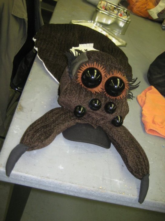
 This year I’m building an encryption device for my Retrotechnology Society. If you recall last year 6 of my friends/relatives were “antecedently” inducted into a secret society. The only down side being that the society was so secret that I never heard back from anyone. This year I’m going to change all that by providing them with this encryption device, so they can communicate with me (and one another) in cipher. Functionally it’s based on the 1850’s Wheatstone Cryptograph, design wise I’m working on spicing it up a bit.

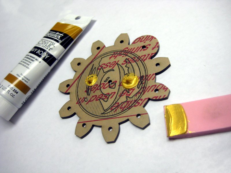


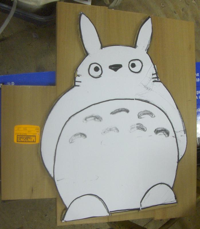
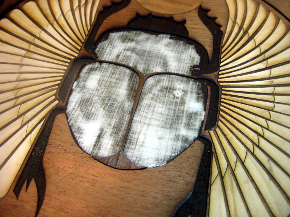
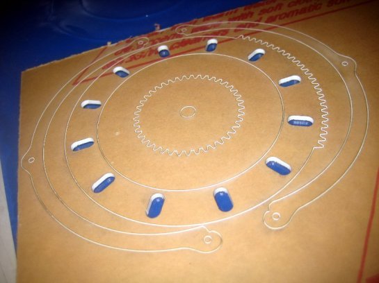
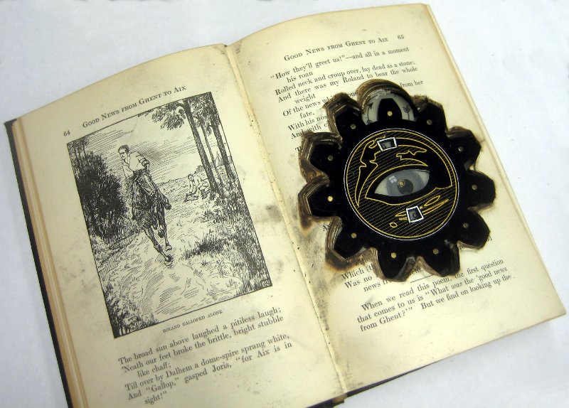
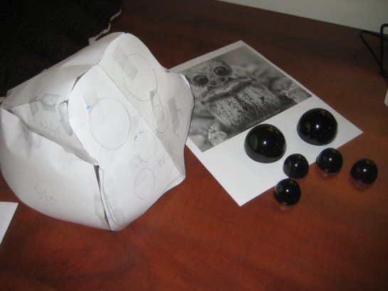
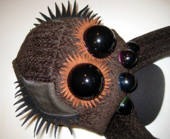
 So this morning I started assembling a final unit. Here’s the parts mostly laid out. They gray part of the eye is supposed to look a bit rough like that. I want the device to seem a bit old, not super crazy snappy new.


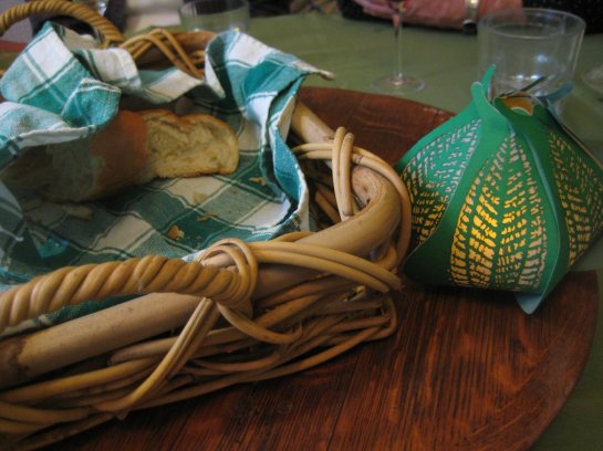
 The other day my son Pioneer brought home a paper lantern from preschool. Around that time we also got some pastries in an interesting paper to-go box that had four sides and folded up into a nice curved shape. That got me thinking that I hadn’t done any paper projects in a very long time.
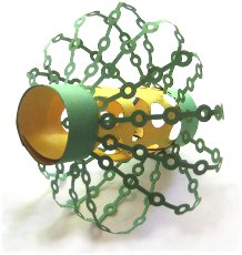 I initially thought I’d make a lantern a bit like the one Pioneer had made, but with much more detailed cut outs. I produced a few little prototypes out of construction paper. I didn’t get a picture of the better lighting bolt themed one, but I did take a picture of this green and yellow one, but wasn’t satisfied with the way they looked kind of spindly. So I thought maybe I’d make a more enclosed lantern a bit like the to-go box I’d seen, but with nice patterns formed by using two layers of paper with the pattern only cut into one of them. I experimented with various patterns, and also started looking for the right overall shape. With paper, scissors and tape I made a number of 4 sided prototypes, and then a 6 sided one. That seemed more pleasing, and I second 6 sided one that I eventually went with.
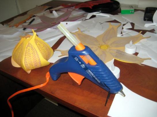
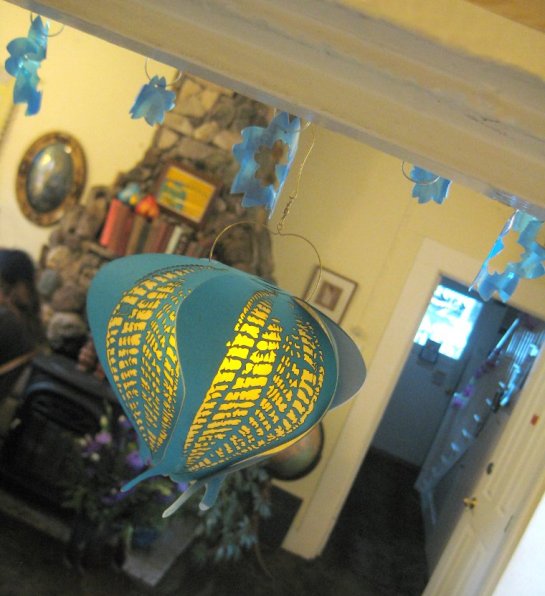
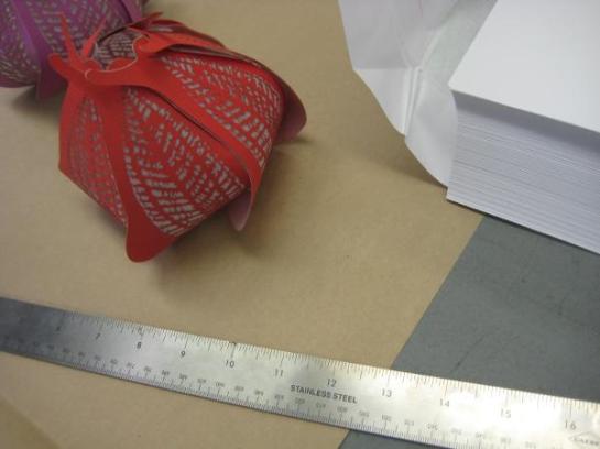
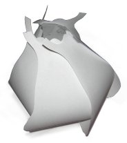 I knew I didn’t want to deal with actual candles, and thought LED candles would be excellent replacements, without the risk of fire and design constraints that would impose. I found Pier 1 Imports selling 4 small LED Candles for $5, so that’s what I went with. When folding up the various paper lantern shapes I realized it was important to do that with a light inside the paper so you could see the patterns that the paper overlaps where forming. I eventually made a prototype where the overlaps formed a flower, but because I was later constrained to some fairly opaque paper for the colored layer of my lantern I didn’t take that prototype any further.
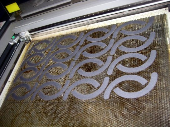
 Time was running out, so I did a quick pattern design based on a leaf, and thought I’d get cutting/gluing in no time. However I ran into a problem. The super detailed pattern took about 30 mins on the laser at it’s highest speed. (Enough pieces for two lamps) I thought I could avoid this bottle neck by stacking up a bunch of paper and cutting it all at the same time. However the massive amount of air flow in the laser chamber and the direct stream of compressed air at the cutting point made it so the paper would not all lay perfectly stacked up, they’d puff apart and chads would fly, and all this mayhem made it ineffective at cutting more then two sheets at a time. I ruined 3 extra sheets of paper on that first run because the lower sheets were somewhat cut, but not well enough cut that the chads would drop out. It was horribly time consuming to try and hand poke/trim out all these suck pieces, and so I decided I really could only cut two sheets at a time.
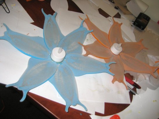
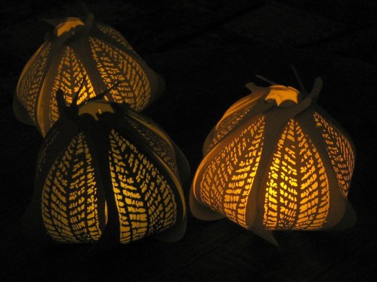
 Then I had to assemble things things. For each lantern there were 6 pieces. Three patterned colored outer pieces and three vellum inner pieces. I used a glue stick to attach the inner and outer pieces together in pairs (only gluing at the top/bottom). I did this because glue stick doesn’t cause the paper to wrinkle/warp the way Elmer’s glue does. Then when I had 3 pairs glued up, I’d glue the base rings of the 3 together with yellow Elmer’s wood glue. (for strength) I’d glue the LED Candle to the center of this stack with hot glue. (Quick, and with good gap filling.) Then after that had set up I did the final gluing of the upper sections. (again with Elmer’s) The final glue step was the most painstaking, but not too horrible.


 I decided on an overall scale for the project, and I was off to the races.