
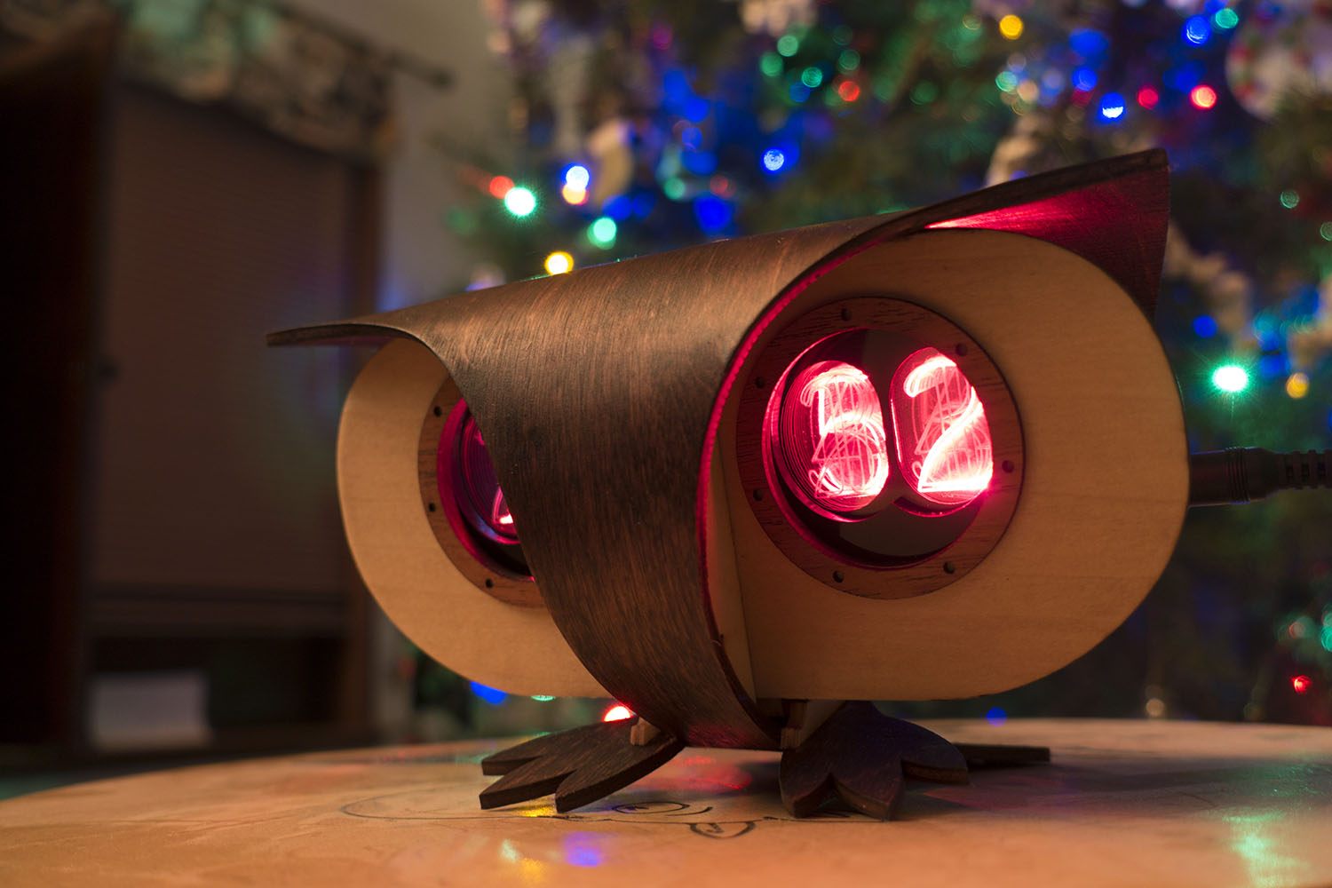
 For Christmas I designed and built six steam-punk owl clocks that have a novel faux Nixie Tube display. Nixie tubes are wonderful with their glass tube bodies and brightly glowing numerals, but think how wonderful a solid-state low-power any color “Nixie Tube” would be!
The basic idea is that you position an LED at the edge of a piece of acrylic that has a pattern laser-etched into its surface, and the LED lights up the pattern. Long ago I’d realized that a stack of 10 laser-etched digits with an LED to light up each digit might have the same visual charm as a Nixie Tube, and the Plexitube was born.
I’m pleased with the way the project turned out. I’ve put the software, circuit designs, and illustrator files up on github. I even made a short video of one of the clocks in action. The project has even gotten some attention from Hackaday and won this Reddit unconventional clock competition. Thanks a lot guys!

At the time it was unclear if light bleed between the layers would make the digits hard to read, so I sat on the Plexitube idea for a long time waiting for a project that could use that kind of display.
Then I went to work at a new company, and I had to spend an entire day listening to benefits summaries and corporate on-boarding. To pass the time, I started to do some sketches of an owl made from only two pieces of wood. I used my Swiss army knife to cut my co-workers’ name tags into owl prototypes. I really liked the design, and I thought it would be perfect for an owl-shaped clock with Plexitube eyes. Would this be this year’s Christmas Project?
I can’t really start a Christmas Project until after the Halloween Costume builds are done, but this project couldn’t really take shape until I’d at least tested the viability of the Plexitube. I figured if I just spent one evening laser-etching a digit stack and holding it over an LED, I could figure out if the displays were going to be an unreadable mess. If it failed, I could pull the plug on the owl idea before they got out of the paper prototype stage. So I spent one of my Wednesday nights making a prototype stack.
 The prototype stack had a lot of issues. The back digits where hard to read, there was a lot of inter-digit light bleed. I really couldn’t say for sure whether this was going to work. That’s pretty much the worst-case scenario for a make-or-break prototype. Really, I should have just stopped then, but I couldn’t stop thinking about the nice owl shapes.
The Impossible Project
Halloween came and went and I needed to decide. I even went so far as to do some prototypes of an alternative project that was much simpler, but I could tell that the owls were the ones that wanted to be made. I’m usually pretty careful planning one of these projects, and never before had I taken on one that had so many BIG unknowns. I’d never worked with surface mount electronics, never bent wood to such small radii, never designed a PCB with a lot of exact physical layout constraints, and never used an in-circuit programmer. I decided to go for it, but I knew I’d have to get first-time-success-lucky on a number of things, and I told my coworkers that I did not expect to succeed.
Two months and counting
 Time to make a lot of quick choices and order stuff from China. I chose the popular Neopixel surface mount LED as my light source. They could be any color and all 40 of them could be controlled using just one pin from my controller. I decided to go with the ATMEGA328p, which is the same chip in an Arduino UNO. I was building 6 clocks, so I’d need 240 LEDs. I ordered a reel of 500 from China, along with some surface mount capacitor and resistor assortments, photo resistors, and some DS3231 real-time clock modules with battery backup. Ordering things from China is very cheap, but it can take a few weeks for the stuff to show up, so I had to get that moving quickly.
Now ordering printed circuit boards from OSH Park takes something like 10 days, so I really needed to get that in the pipe. If the first set of boards were a complete blowout, I could still get a second order in, but I had to hurry.
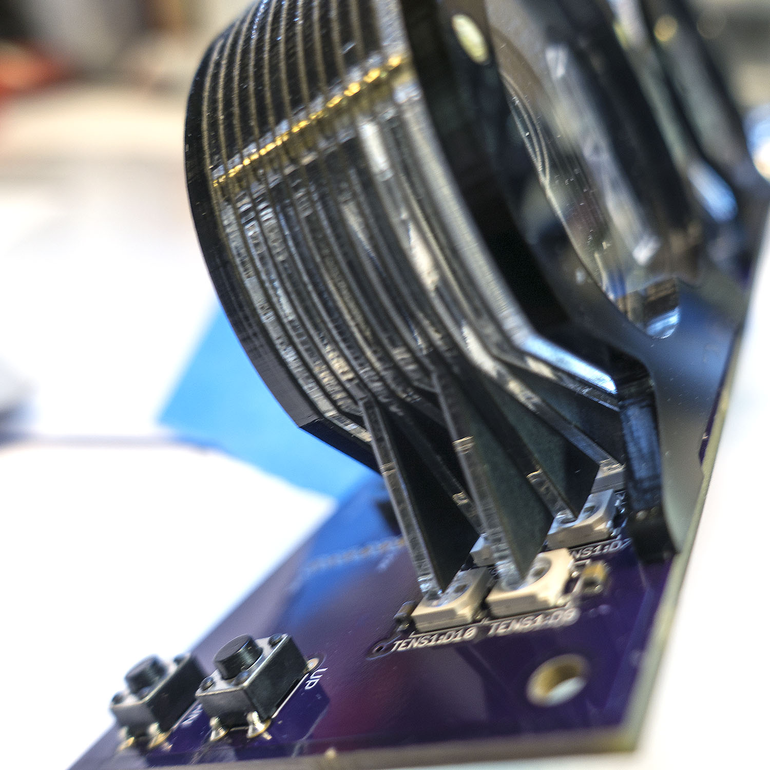 The LEDs I was using are much fatter than that 1/16″ acrylic layers I was using, so each layer needed to have a sort of integrated light guide leg that would stick out and sit directly above the 3 tiny color chips inside the LED. The alignment had to be exact. So I measured an 10-layer alternating stack of acrylic and black card stock to get the exact spacing, and then I had enough info to begin laying out the PCB.
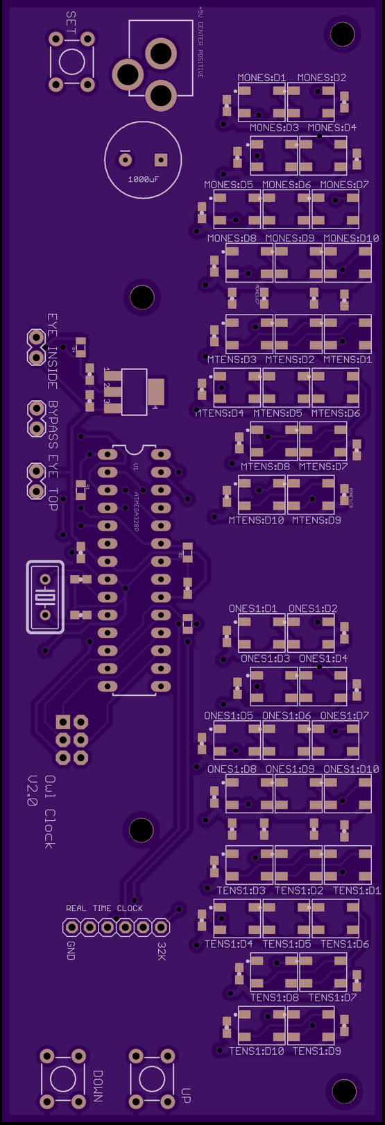 I used Eagle CAD and finally had to spring for the non-free version so I could work with more than one page of circuit. I had to use some tricks with the Grid to get all the LEDs laid out in the exact right locations. After a full weekend of fighting with Eagle, I had something I could send off to OSH Park. I also quickly ripped one eye segment out into another file and ordered 3 small “test boards,” so I wouldn’t have to do my first attempt at reflowing a surface mount board with one of my giant and owl boards.
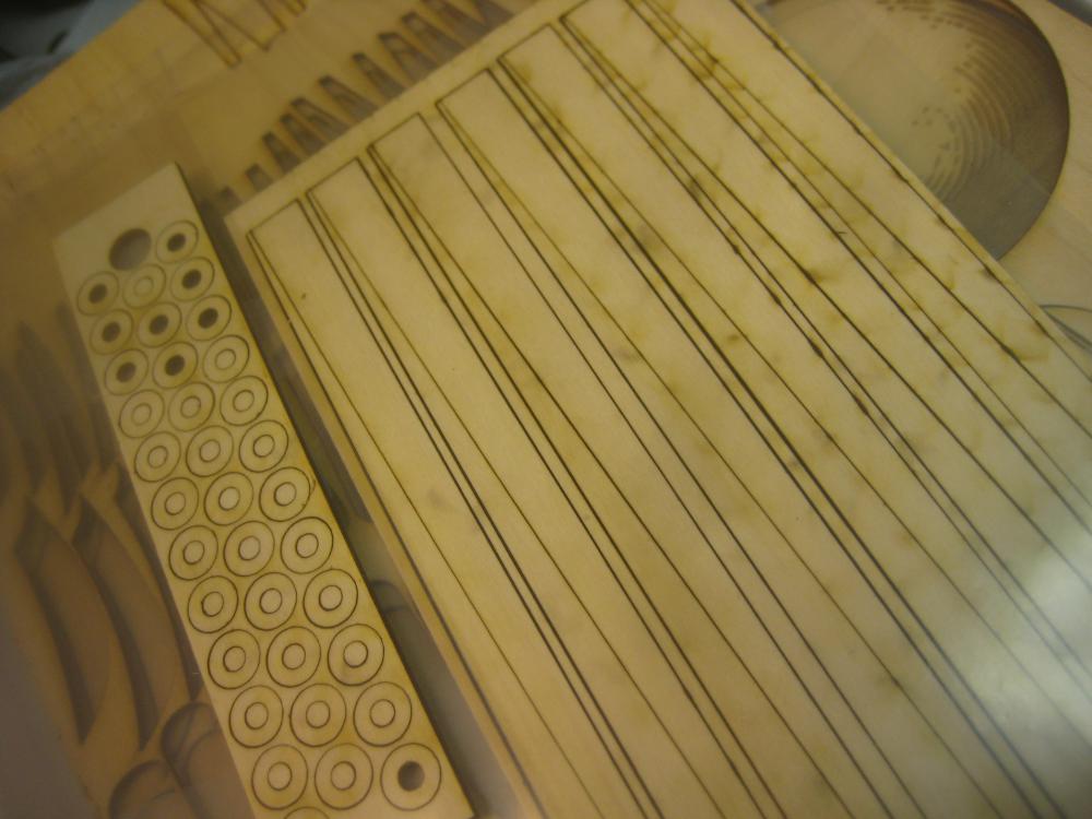
Then it was back to working in Illustrator on the design for the acrylic digit layers, black card stock separators, etc. I customized the digits of a font to make them slimmer. All the digits obstruct one another, so I wanted something that was lovely, but was mostly empty space so other digits could shine though. I also did some tricks like make the zero (which is in the back) a bit bigger/bolder so it would still read well though all the other digits.
Secret Symbols
Now on a clock there are 4 digits, but not every digit needs all 10 numerals. Heck, the tens of hours digit only really needs a 1. That leaves 9 layers for other special non-digit things. I could, in theory, have put some extra digits in the back of the tens of minute digit since it only goes 0-5, but I decided if I was going to be showing other info in those lower digits, it would be better to have all the digits there. I also decided to keep the 2 in the hour-tens digit so I could support 24-hour time in the future, and show a full year like 2016, etc.
I wanted to show the phases of the moon, sunrise and sunset times, moon rise and moon set times, etc. I used 6 of my 8 free digits doing the arcs of the moon. Because all the layers are at different depths, I staggered them so the arcs actually make a 3D sphere shape with the middle most arcs at the front. That left me with 2 layers. I used one for a sun outline that could be used along with the arcs to show things like the equinoxes/solstices.
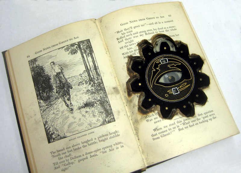
The Magic Eye
That left me with only one free layer, which I used to add the outline of an eye. I realized that the arcs could be used to animate a slit-pupil eye looking back and forth. Of course I needed that! My owls eyes have eyes?! Yes … yes they do.
Plexitube Assembly
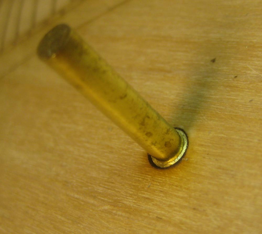
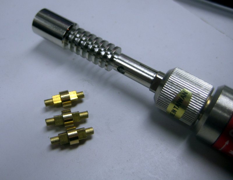
 Each eye element can display two digits, and they are laboriously assembled by stacking 20 digit layers and 20 paper masks on 4 brass pins in careful sequence. Thankfully, the digit layers were fairly easy to keep track of because they already had digits etched into them! Each acrylic layer has to have its protective plastic peeled away, and its etching scraped and dusted. Because the pins are press-fit, I had to carefully push them down on the pins without cracking the 1/16″ acrylic. The first stack took me 2 hours to assemble. My finger nails were frayed from all the plastic peeling and I had 11 more elements to make. What had I gotten myself into?!

First Reflow
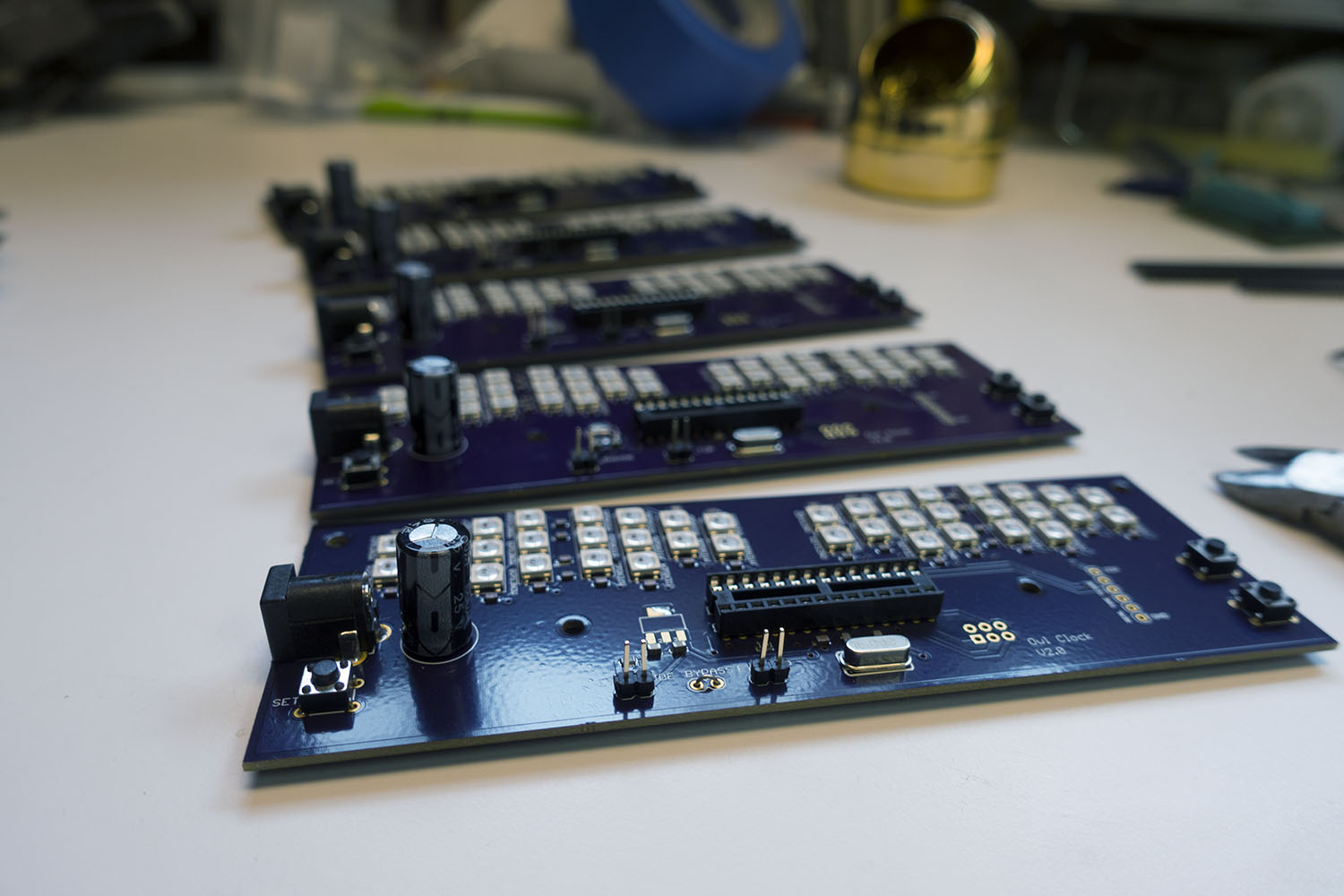
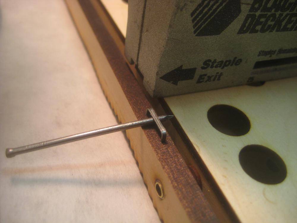
 Finally the owl boards came! I had also ordered a solder stencil from OSH Stencils. When making a board like this, the basic process is a bit like silk screen printing. You position the PCB under a stencil and squeegee solder paste though the stencil holes onto the board. Then you place all the itty-bitty components onto the board with tweezers. Finally you oh-so-carefully put the board in an oven and heat it up until the solder paste melts and the parts all snuggle down exactly into place via surface tension. A while ago, I had built a special computer-controlled toaster oven in order to do just this process, but I had never used it!
 I kept waiting for my test boards to show up, but eventually I gave up and decided to do my first reflow on one of my giant and indispensable owl boards. I populated the board, put it in the oven, and pushed the button. Then I held my breath as the oven went though its 3-minute cycle. Success! The board came out looking perfect! It looked like something totally commercial, not something I’d made with tweezers and a toaster oven. MAGIC! Surface mount is awesome. I’m never going back!
 Ok, so the board looked like it was all soldered up, but would it work? I hooked the LED chain on the board up to an Arduino UNO (remember how those NeoPixels can be driven by just 1 LED?) and some quick code showed that all the LEDs were working! I blinked each one red-green-blue to test and they passed with flying colors! *phew*
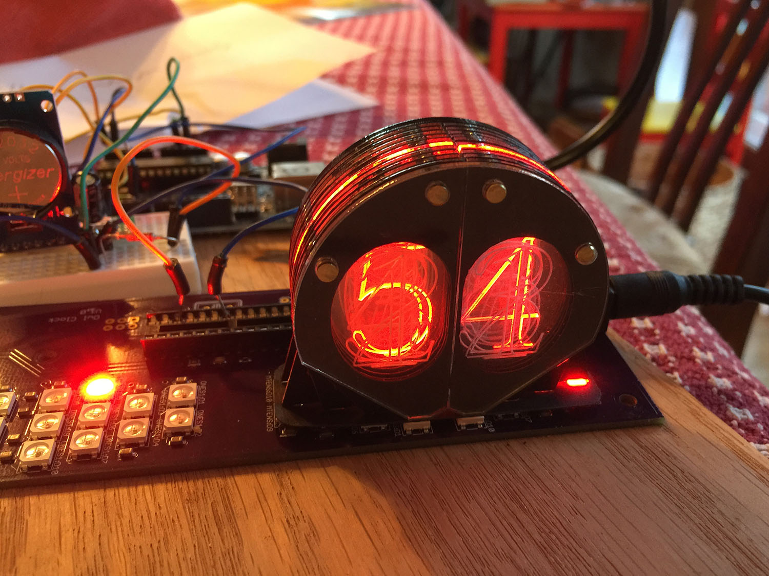 Now for the real question: would the digit display actually look good or was the whole thing going be two months of work for an unreadable mess? I wrote some code to cycle though the numbers and positioned the eye module over the LEDs. It sort of worked, but it wasn’t great.There was quite a bit of cross lighting between digits, especially between digits 1 and 2.
I was extra sad I’d left that 2 in the hour tens digit. No one wants to look at a clock and not be able to tell if it’s 11:14 or 22:14. Something really needed to be changed. But what? I did, however, decide to get my second round of PCBs made. OSH Park sends out 3x boards, so if I wanted 6 by Christmas, I’d have to order the second round pronto.
 I spent an evening designing a nice owl icon to put on the second round of boards, added two regulator bypass pins, and then sent the thing off. No time for anything fancy. It turns out the icon was a fail. Even though I followed OSH Park’s guide lines it did not render properly.
Eerie Is Good
 One thing I did notice while I was running that test is that although the digits were not yet crystal clear, the whole thing had a very eerie feel to it. It was almost as if I couldn’t quite tell what the heck kind of technology I was looking at. It sure didn’t look like LEDs. The layers of acrylic have a wonder full “hall of mirrors” effect on the lit segments. I also noticed that the light bleeding off the tops/sides of the eye element were kind of hypnotic to watch go through their sequence. I had originally planned to cover the elements with a ridged copper cylinder segment, which would have looked steam punk, but not as strange/cool as that bleeding light. I decided to leave them uncovered.
Back To Body Work
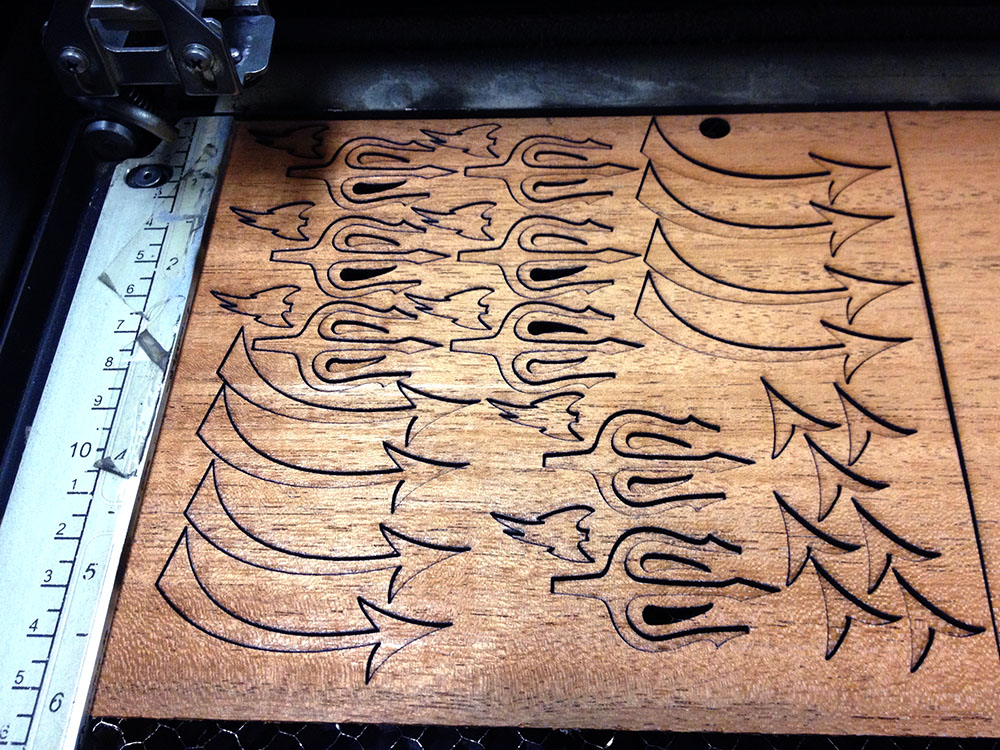
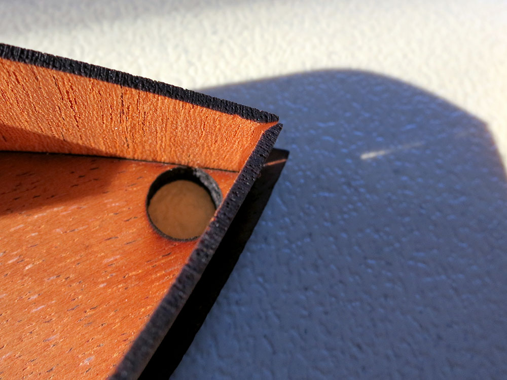
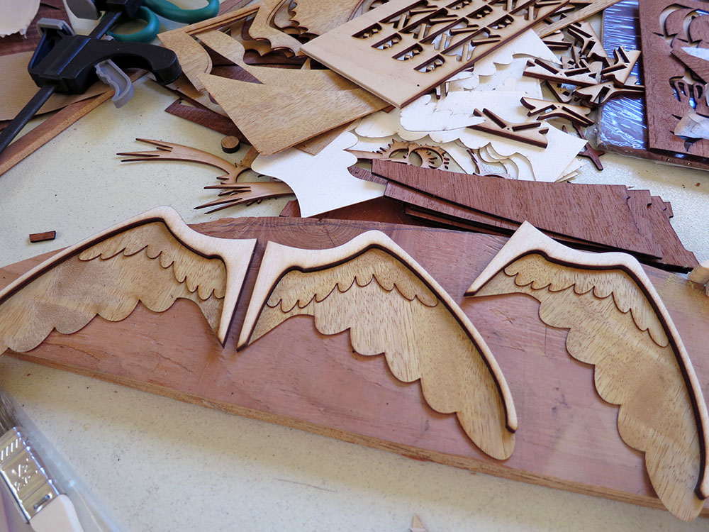
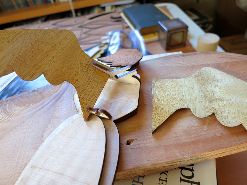
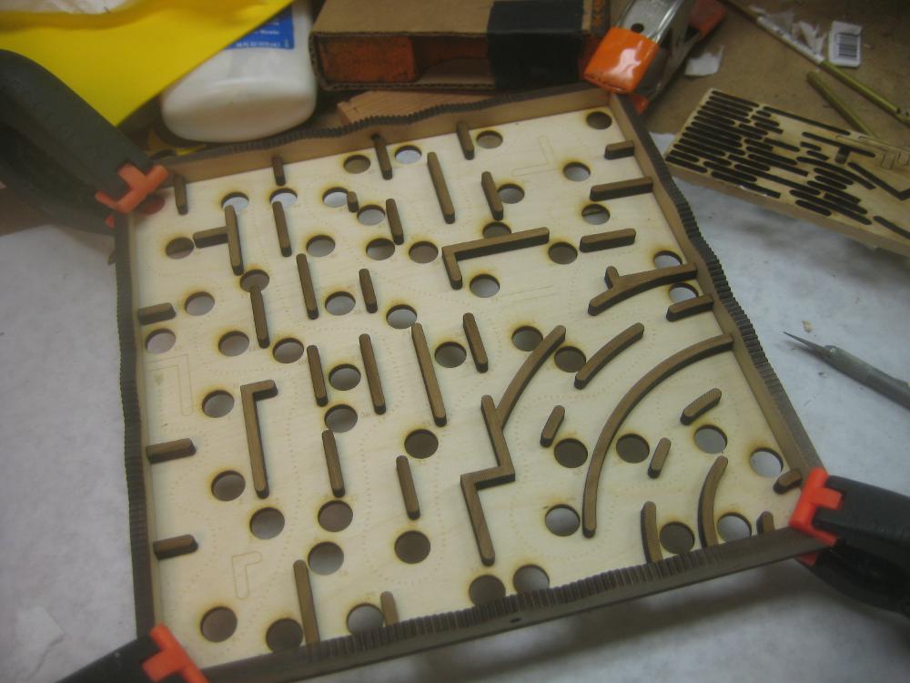
Now that the boards and the eye element design were mostly settled, I had to get back to figuring out how to design the bent body of the owl. I did a second pass of designing the body in cardboard. I knew that trying to bend 1/8 plywood into a loop maybe 3 inches in diameter was going to be tricky and might be impossible. In a recent build, I’d used laser “kerf bending” to make it easier to bend curves in thicker plywood. Could I take that to an extreme? MicroKerf Bending™? I tried spacing the kerf cuts .1″ apart, cutting almost all the way though the plywood. The results where a satisfyingly bendy piece of wood. Still the owl has some very wide sections at the top of his eye arches and those were still quite stiff. Too much variation to be able to bend into a loop.It would have been nice to write some sort of script that would space the kerfs closer/wider based on the overall width of the piece, but I had to settle for just doing a few different spacings by hand.
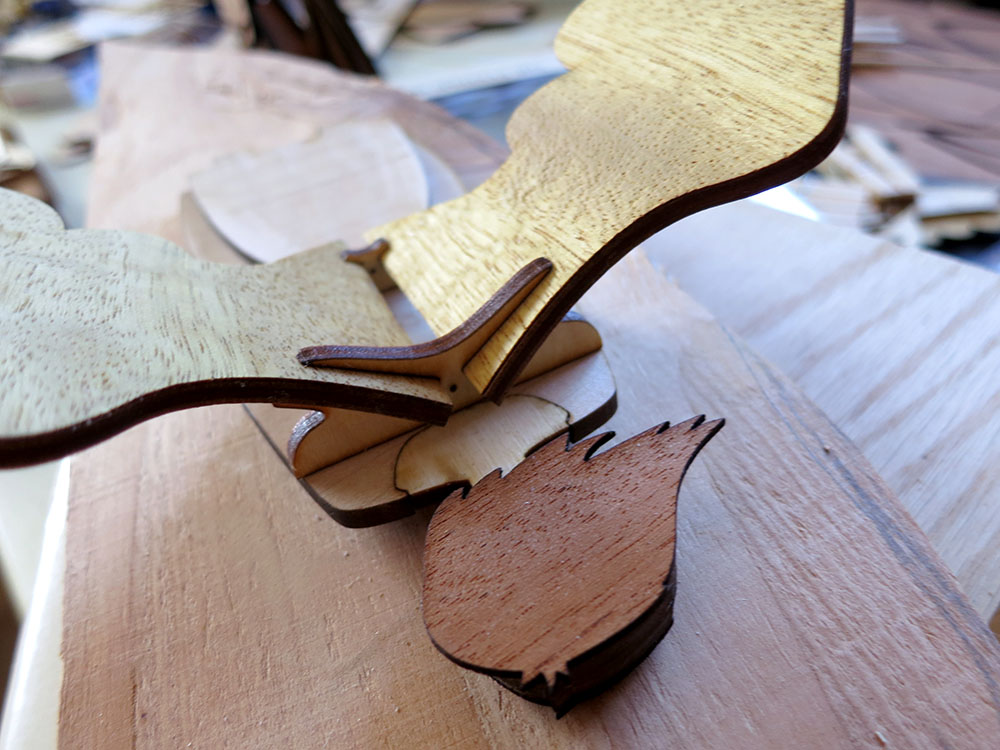
 The brows above the eye were delaminating when I’d apply the bend. That was bad. I fixed it by pre-sanding the upper layer thin in those areas and by putting a few little spring clamps on those edges during the bend. That solved the problem, but all these iterations on the body design were burning up time at a crazy rate. Would I make the Christmas deadline!? Here I’d been thinking I was saving time by having most of the owl form come from just one piece. So wrong.
Steaming and Clamping
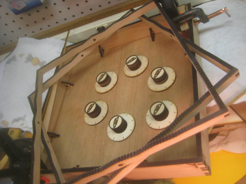
 I built a clamping jig out of a big board and carved away clearance for the owl feet. I’d steam an owl body in a pot on the stove and then bend it with my gloved hands whilst racing out to the garage to clamp the body around the face in my special jig. The first time I did this the face of the owl split in two! Yes, when the body is looped back on itself and clipped tail to feet the forces on the face are nice and balanced, but while you’re bending that around the forces on the face are actually pretty big. So I changed my clamping jig so it would support the face during the bend. Finally, it worked!
 I had a lot of other little issues. I had to add some “foot prop” pieces so I could have a way of evening out feet after the main clamping was done. I thought I’d be able to adjust the owls stance by adjusting the tail angle, but a sort of scissoring action made it so any amount I pushed up the tail also pushed up the feet, canceling out the adjustment. So the owls look down a little bit more then I’d like. That’s okay though because they like to nest up high.
 I wish I could have used 1/8″ mahogany plywood. Then I wouldn’t have had to deal with staining the outer body. However, that’s not something I can get locally so I was stuck with stain. I hate stain. I tired pre-staining, which gave nice crisp edges at the stain boundaries, but that made the gluing a lot weaker. I tried post staining with with pre-clear coating areas to try to reduce bleeding over, but it still bled some and required lots of awkward sanding to fix. If I had it to do again, I’d try to get hardwood ply. I did eventually get them all glued and stained.
The Secret Sauce
 I’d been thinking about my eye element problems. How could I improve the contrast? I already had black card stock all over the place blocking as much light as I could. I realized that as tight as the fit was around the card stock, there were still micro gaps, and the light leaks I was seeing were probably coming right up from the LEDs and into the clear bottoms of the other segments. I decided to use a small brush to paint some black acrylic into those areas! EUREKA! That fixed the problem entirely and now the displays looked great.
Christmas Eve
 It was Christmas Eve, and I was still clear-coating owl bodies. Applying wood finish on Christmas Eve is par for the course for me. The big issue was that I was still driving the displays from a separate Arduino and hadn’t fired up the on-board computer at all. I spent a while reading about fuse bits and fighting with boot loaders, and fiddling with Arduino IDE config files. Had I made some mistake with as-yet-untested parts of the PCB? Could I get lucky one last time on this “impossible” project? Yes! At last, I was able to program the chip on the clock board, get the real time clock synced with Greenwich Mean Time, and put enough code in the clock that it could actually display the time! The clock could go under the tree.
Software in the New Year
Early on I had decided to punt on all but the most basic software until after Christmas. I had pages of ideas on fancy software features, and I knew I’d have enough trouble just getting the things physically built by Christmas. This was going to be a Christmas gift with an eventual “firmware upgrade” gift chaser.
 I knew there was going to be a lot of software, so I wrote a iPhone owl clock simulator to give me an easier platform to develop some of the code. I had been reading Jean Meesus’ Astronomical Algorithms, and I wanted to have the clock not only show the phases of the moon, but be able to display sunrise/set times and moon rise/set times.
I had included a light sensor on top of the clock so the clock could dim a bit when it was in the dark, but it could also tell if your hand waved over the clock and maybe then it would cycle though showing the sun going though sunrise colors while showing the sunrise time and the show the sunset time while cycle though the sunset colors.
Color Picking the Old Fashioned Way
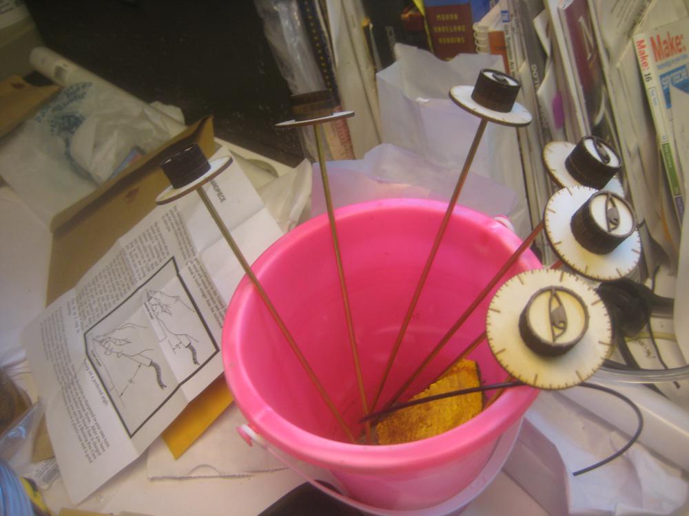
 I really wanted to use nice colors in the clock, but just choosing 3 numbers for Red/Green/Blue doesn’t tell you what those are going to look like in the final display. I needed a way to search for good colors. So I made a super simple color picker by hot gluing three potentiometers to a board. I used an Arduino UNO to read the three RGB values and display the color on a jury rigged LED + acrylic digit. Go Go gadget gaffer’s tape! The program would print the values out to the serial monitor. That way I could find just the right pink by fiddling with the knobs and then write down that RGB triple from the screen. I used that to make a whole pallet of colors I liked.
The Trouble With Doubles
The big problem was that most of the Astronomical Algorithms need double precision math. The solar system is big and you need the precision, but the Arduino tool chain doesn’t have real double precision math. I spent a while (stupidly) writing a math lib that did approximate double precision math using two single precision float values based on this paper targeted at GPU computation with floats. I did get the math working, but to my horror, I discovered that the code it produced to compute the equinoxes/solstices was so huge that it didn’t fit into the 32k of memory on the ATMeg328p. That was a huge waste of time. I did, however, use the code to generate the next 100 years of solstices and equinoxes and compress them down into just 100 bytes of Progmem, but the sunset/sunrise times were doomed. I went back to some still usable moon calculation code so the clock can show the current phase of the moon.
Then I wrote a lot of silly features. On the clock recipient’s birthday, it displays in their favorite colors. (And on their kids’ birthdays, their kid’s favorite color, etc)
I wrote all the code to set the time/date/gmt offset with nice auto repeat ramp ups and useful icons. (When you’re setting the month a sliver of moon shows, when you’re setting the day there’s a sun icon, etc) I even used the right arc of the circle to show AM and the left arc for PM like they were the first and second parts of a 24 hour clock face. Not that I expect people have to set the time/date much, but a clock needs to do that.
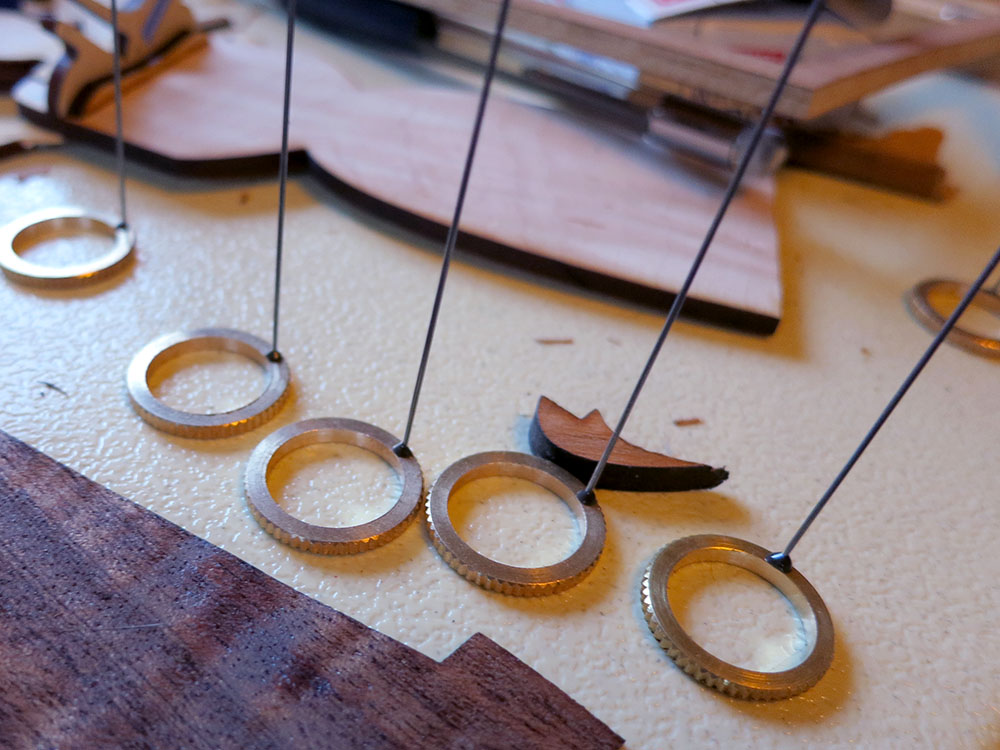
The clock counts down to midnight on New Year’s Eve and shows fireworks and a spinning golden globe at midnight. On JRR Tolkien’s birthday, the the eye of Sauron looks around and sometimes a golden ring spins and the digits are red and fade up and down like like a breathing beast. etc. I don’t want to give to many surprises away.
Needless to say, there are a year’s worth of Easter Eggs in the clock code, even on Easter.
Two Words “Optical Theremin”
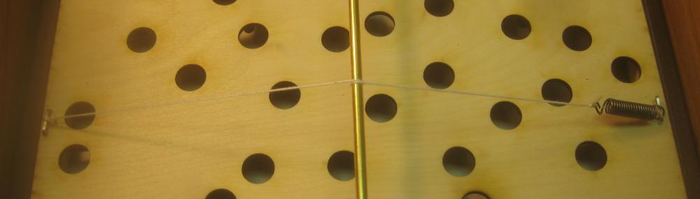
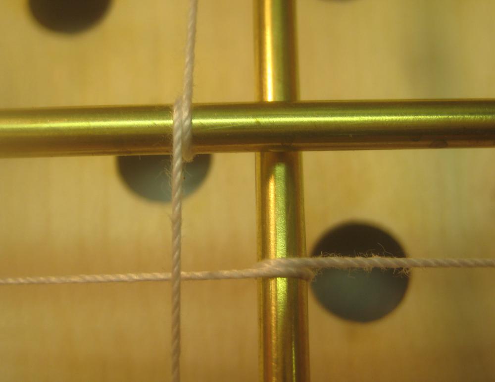
 When I was working on the auto-dimming feature, I wanted to have a direct readout of the light sensor, so I could fine tune a mass/spring system for the dimming rates. When I first hooked it up, I realized that with a much stiffer spring it was pretty neat to play with. You’d wave your hand over the clock and the digits would smoothly go up and down. It was kind of mesmerizing.
I was showing it to a friend, and when I started waving my hand around he said, “Wait, it has a Theremin too!?” and the Optical Theremin was born. I hooked that code up to the hue of an hsv conversion and now when you press the down button, you get one minute of “Optical Theremin” where waving your hands around changes the colors and numbers in a soothing and lovely display of Plexitube awesomeness.
It’s hard to stop writing code for the clock, but after the “Optical Theremin” feature, I started getting close to the memory limits and I decided to call it quits. It was time to give out festive springtime firmware upgrades! I had been trying super hard to have the code all done before the spring Daylight Savings Time change because people had clocks they couldn’t set! I only missed that deadline by a week. I blame double precision!

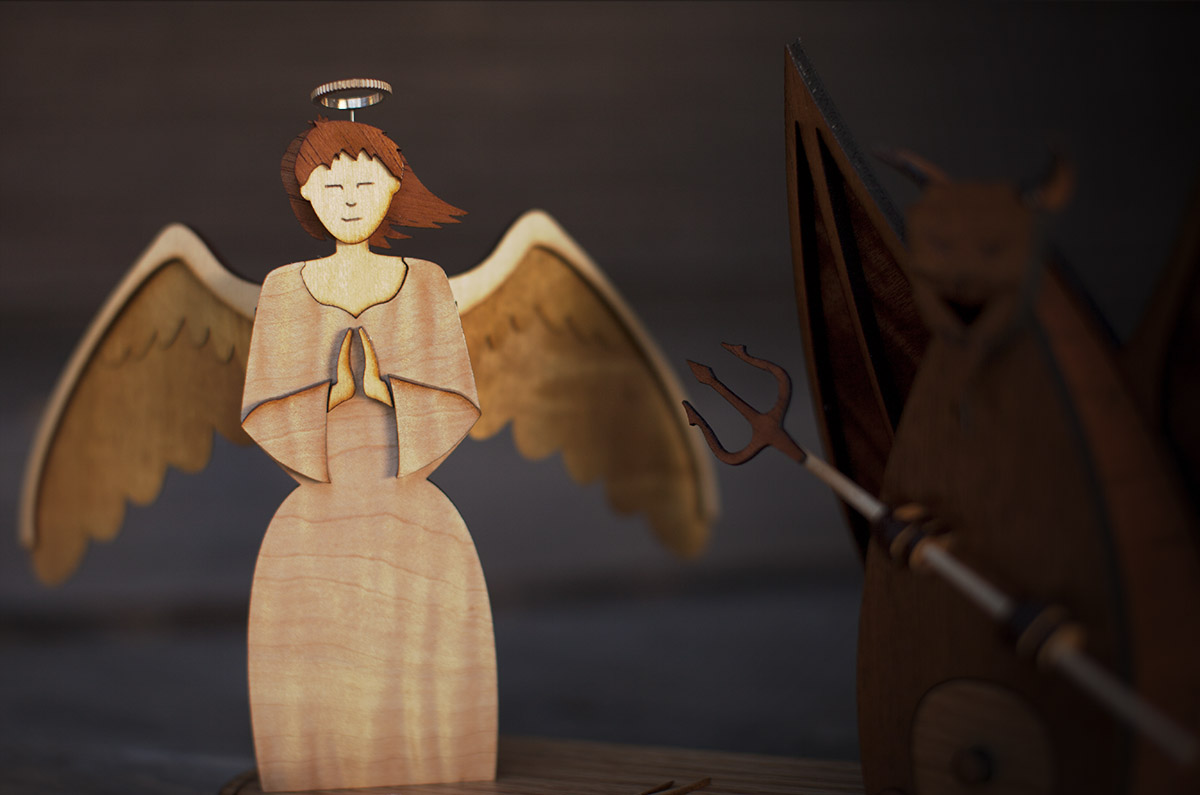
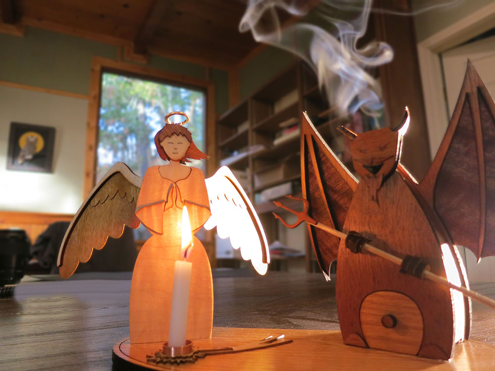
Clarence was starting to think that perhaps this hazing ritual was going a bit too far…


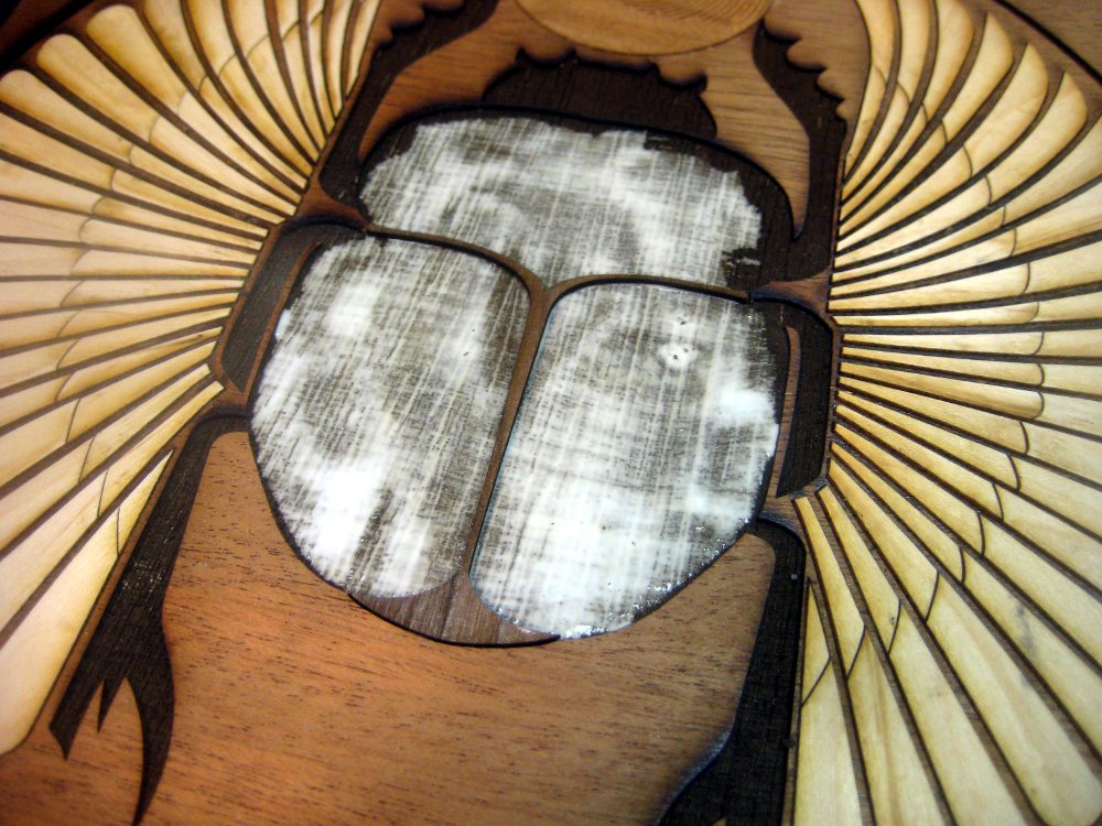
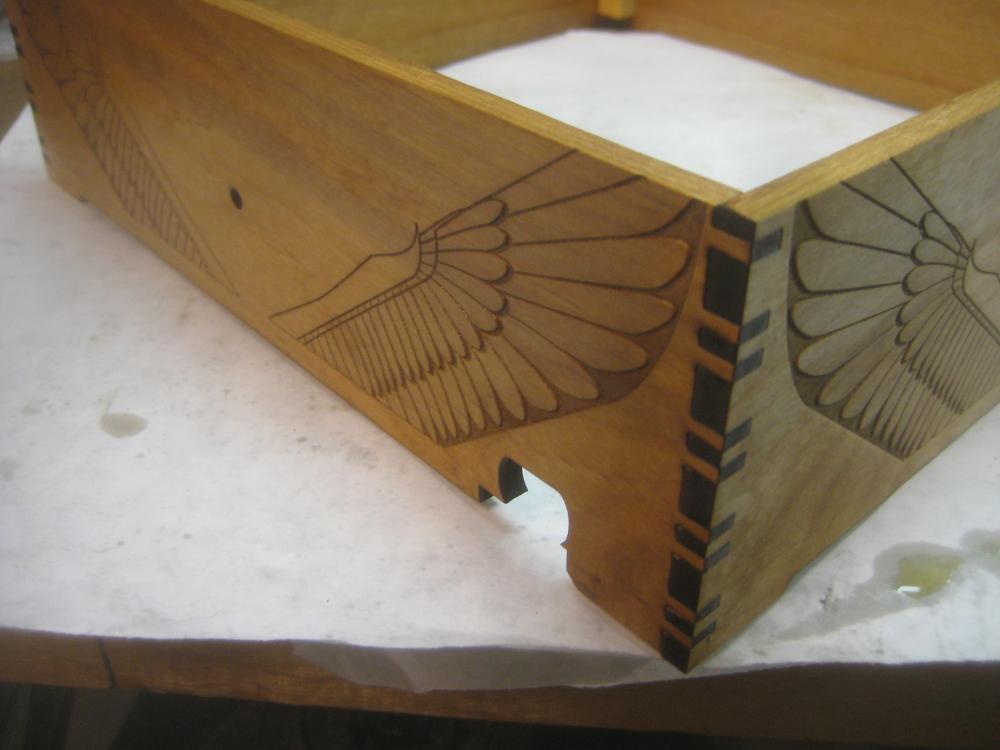
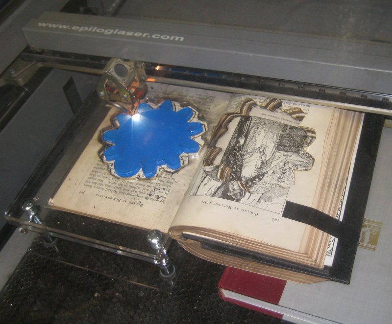
 The 60watt laser deep etching the scarab into the lid.
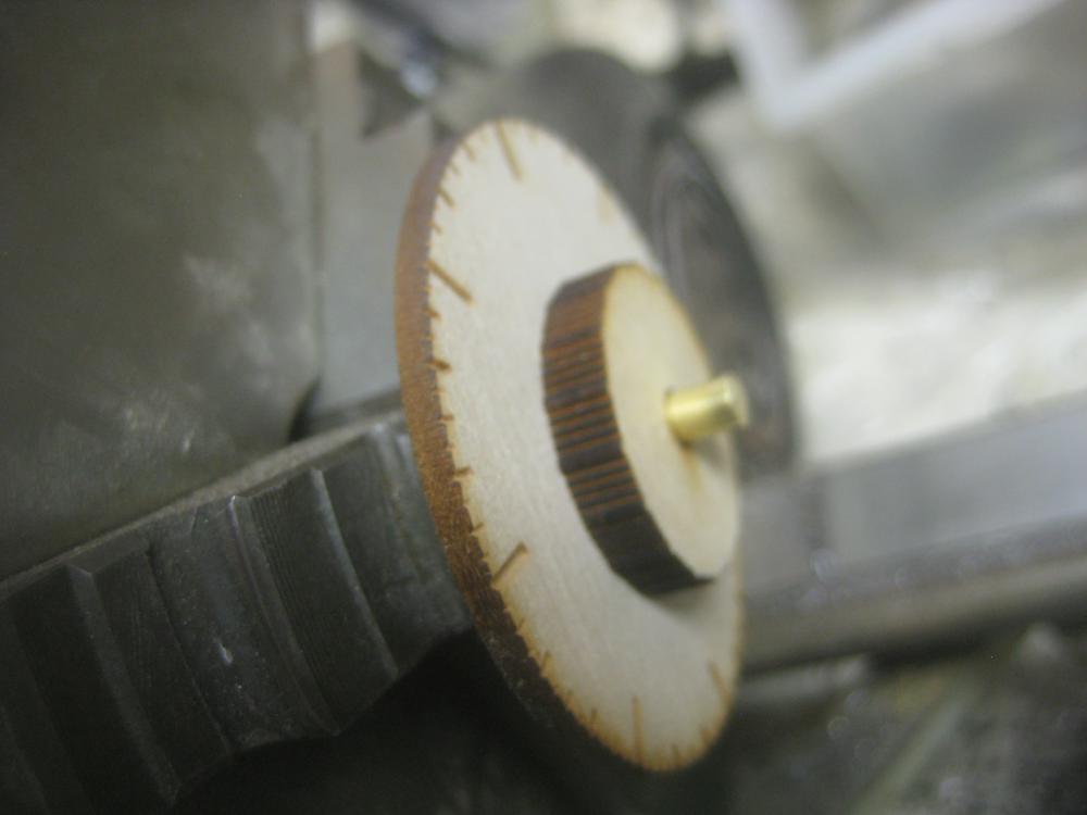
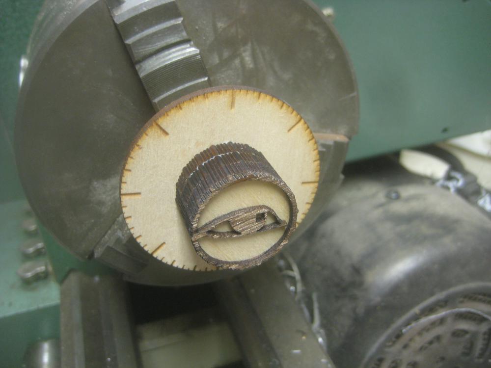
 The laser etched ball glued into the lid
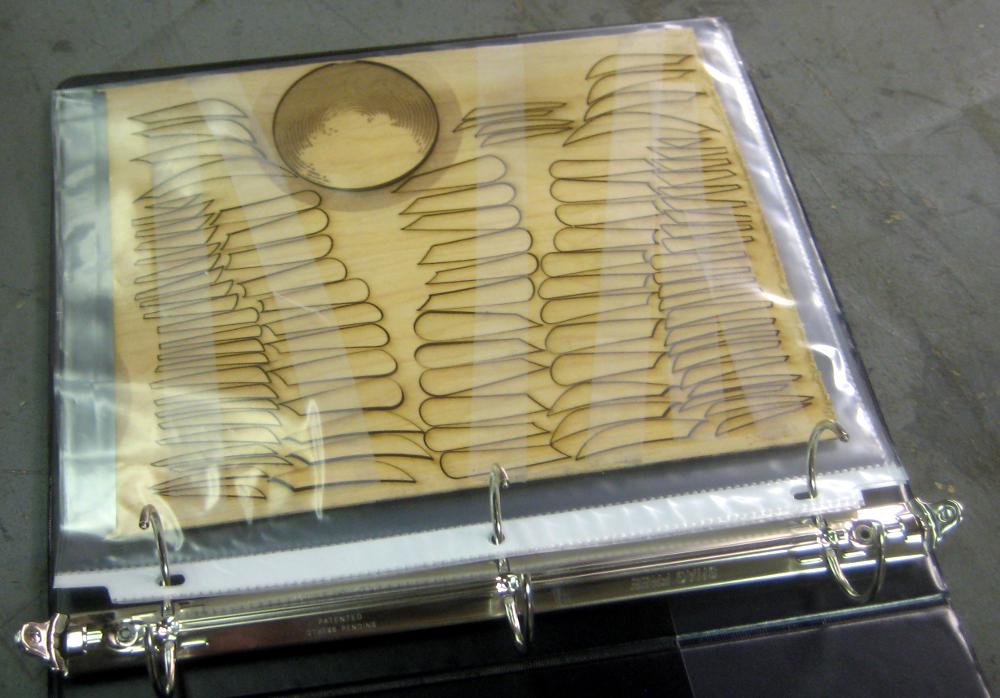


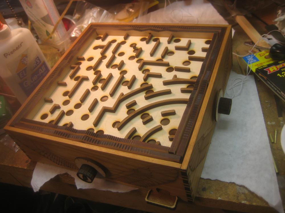


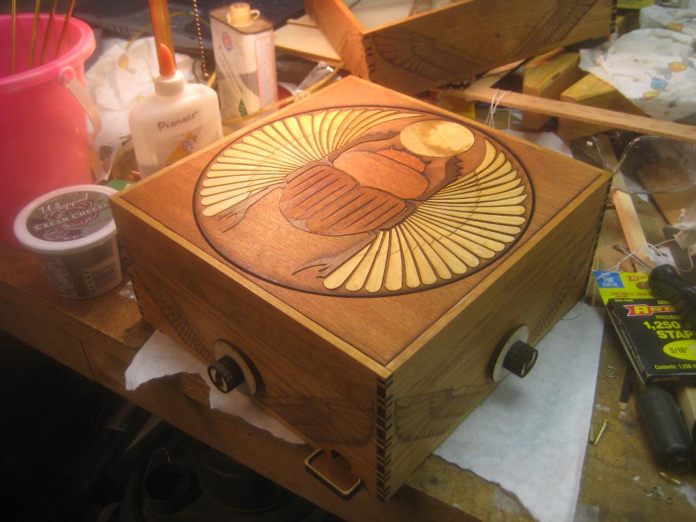
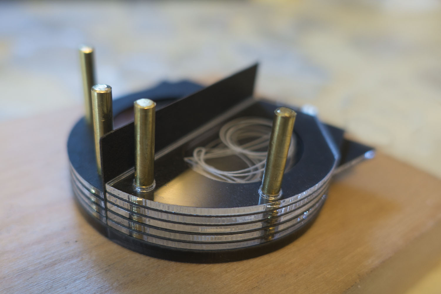
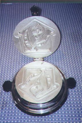
 This year I’m building an encryption device for my Retrotechnology Society. If you recall last year 6 of my friends/relatives were “antecedently” inducted into a secret society. The only down side being that the society was so secret that I never heard back from anyone. This year I’m going to change all that by providing them with this encryption device, so they can communicate with me (and one another) in cipher. Functionally it’s based on the 1850’s Wheatstone Cryptograph, design wise I’m working on spicing it up a bit.


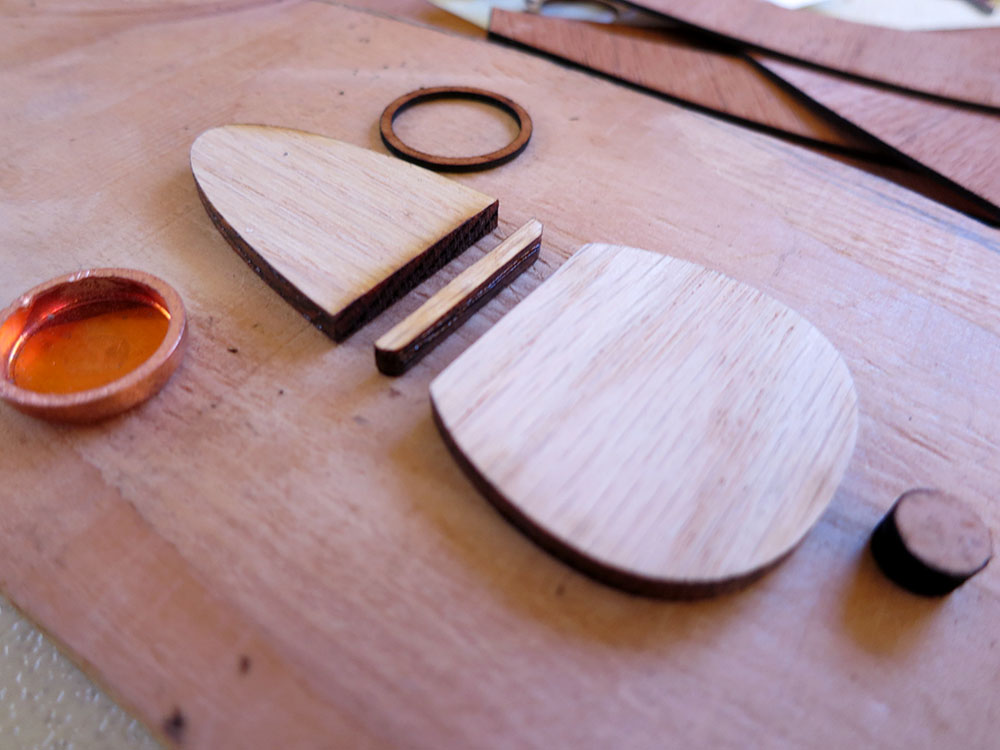
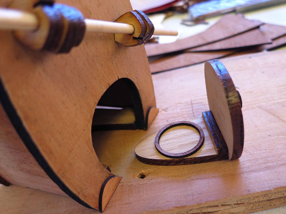
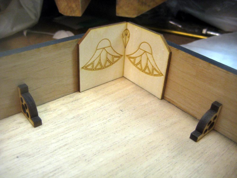
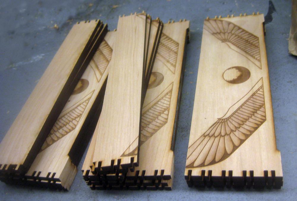
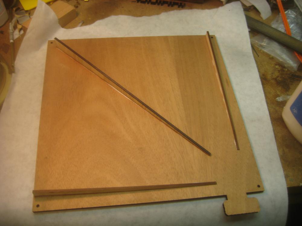
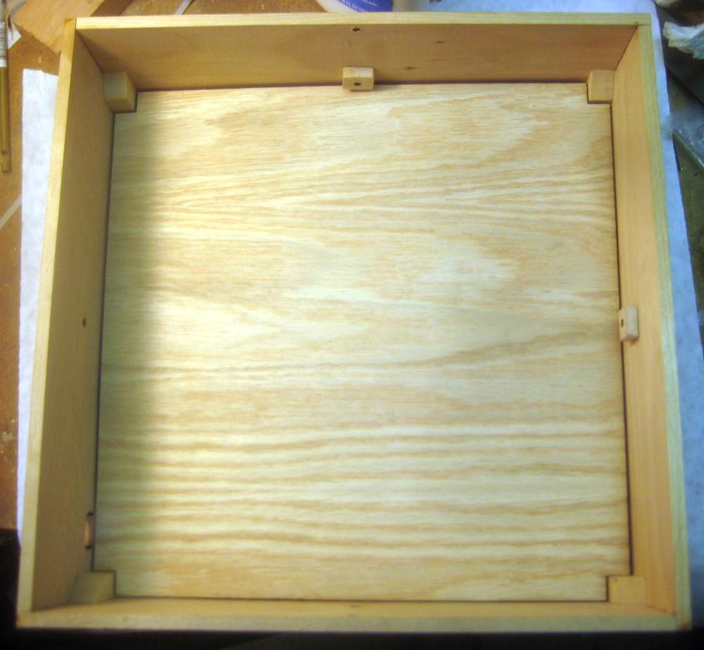
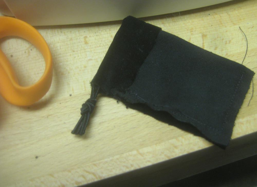
 So this morning I started assembling a final unit. Here’s the parts mostly laid out. They gray part of the eye is supposed to look a bit rough like that. I want the device to seem a bit old, not super crazy snappy new.


