Making a DIY Computer Controlled Loom

Weaving on a loom is fun. I gave my son a simple loom for Christmas, and he wove an entire scarf on Christmas Day. This got me thinking about building a computer controlled loom, maybe one that could weave any pattern imaginable. I liked the idea of taking software back to its very origins with Jacquard and the original Jacquard Loom. I also new there’d be lots of interesting design challenges.

In mid December, TechShop had filed for bankruptcy. My annual Christmas Project was in full swing, and the loss forced me to “Cancel Christmas”.  I was in shock. I’d been using TechShop tools/space for 10 years, and no longer having access to their lasers, Industrial Sewing Machines, etc was paralyzing. By Christmas day, I was starting to recover and was looking for a new project. Hopefully, one that could use the PCBs that I’d already designed for my canceled project.

I still had access to a 3D printer.  Could I design a mostly-3D-printed loom that used the boards’ 3-stepper motor controllers and bluetooth LE?  I’d give it a shot! The basic idea I had was for a 2-motor loom.  One motor would sweep through a bunch of cams, and the other motor would set the position of each cam in turn.

I took the basic specs of my son’s loom as a good starting point for basic size/layout. His is a 10″ loom with 8 threads per inch, so each control section of the loom would have to be 1/8″ wide, and there would be 80 of these sections. An initial sketch of the mechanism indicated 7 parts per section, so the loom would have more that 560 moving parts that would all have to operate flawlessly time after time, row after row, 100s of times per piece of material.  I told my friends up front that it seems impossible and that this thing was never going to work, but working on the design would be really fun and get me out of my post-TechShop project funk.

Now real weaving is an art that involves rhythm, consistency, and pattern. This would never be that. The time to update the cams would be too slow for any real rhythm, but there might still be some fun art and process to it, and stringing up the loom would be quick and easy in comparison to warping a traditional loom. I also had some ideas for programatic pattern generation.  Wouldn’t it be neat to weave out something unexpected? Discovering it row by row? That sounded like fun to me.

A much faster system could be built with 80+ solenoids or something, but that didn’t really appeal to me. It would drive the cost way up and certainly wouldn’t take advantage of these circuit boards I had lying around.

The Big Idea

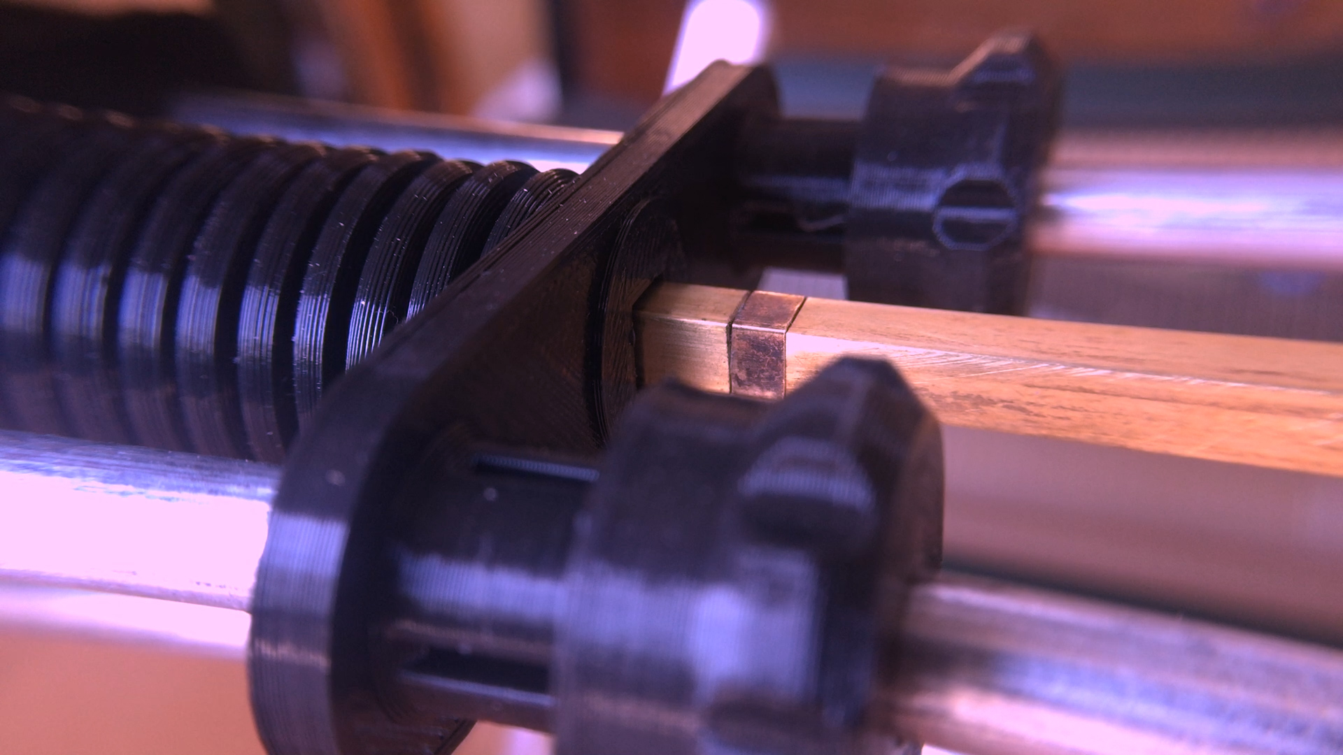
At the heart of the loom is a long row of cams sitting on a square shaft. In order to not have this giant row of cams jamming up horribly, the cams would have to have almost no load. The square shaft locks most of the cams in position but has one section that can rotate to spin a single cam. The main idea was to have the cams not do the lifting and lowering of threads directly, but to have them shift some hooks back and forth. If the hook was over a bar, then the bar could do the work of raising and lowering the threads.

In order to be able to pull threads up or down, I use a second set of hooks and a teeter-totter arrangement. With a second set of bars and hooks, this also makes it very easy to invert the pulling up/down pattern, so an alternating weave requires no change in the cams or hook positions. It also avoids extra loads imposed by something like a per-thread return spring or weight and doubles the distance between the threads.

At first I worked on getting the carriage working. It had to slide back and forth smoothly with little backlash. I did some initial prototypes using just 1/4″ bronze bushings and flat end caps. These basically jammed all the time since the 3D printed flat plates could easily flex enough to take the bushings out of alignment. I changed the design to be much stiffer and to use one pair of linear bearings with a larger main shaft that does all the load bearing and a second 1/4″ shaft with no bearings at all that is just provides additional rigidity and alignment.

Would it work at all?

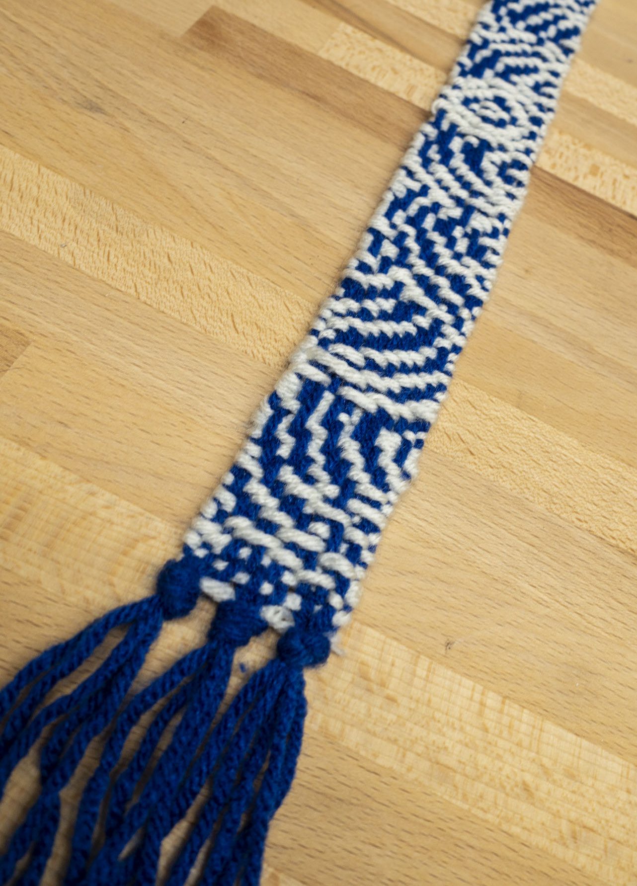
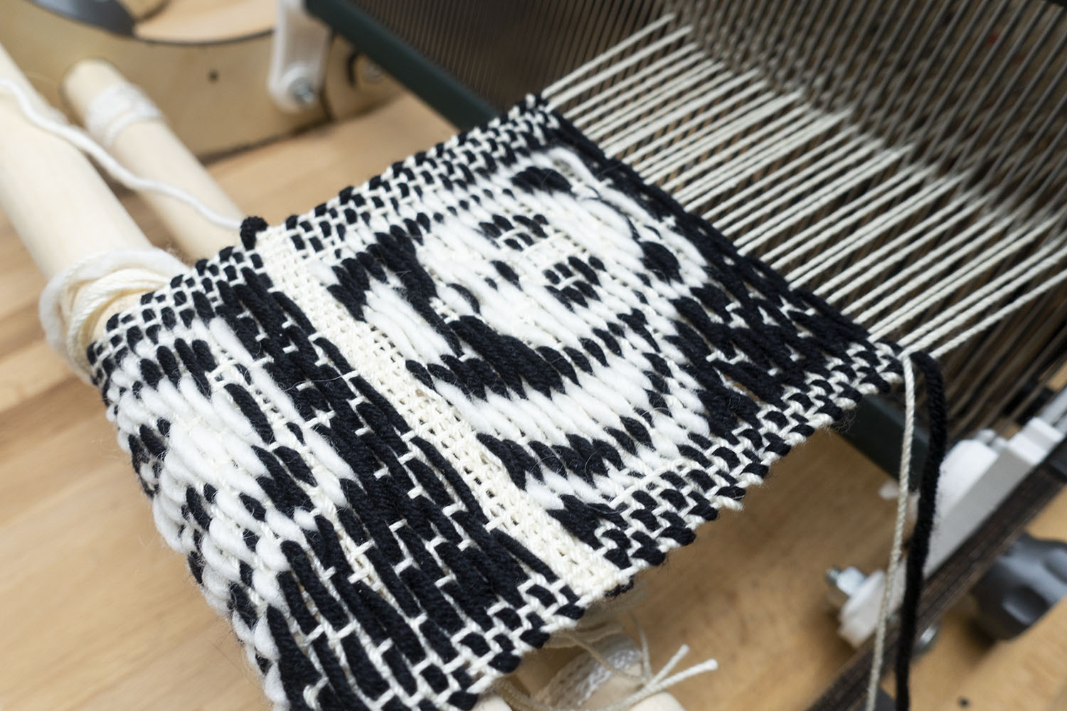
Even though the carriage movement back and forth was now working without jamming, the first time I tried to rotate a cam and seek to the next cam caused a horrible jam. The issue was that after driving the cam there’s still a lot of load from the cam on the square plate, so when you try to seek to the next position that load makes the cam really want to jam on any imperfection between the rotating square segment and the rest of the shaft, and those loads keep adding up as you rotate more cams. Thankfully this was easy to fix in software by overshooting a tiny bit and then returning so there was no longer any load from the cam before trying to seek to the next position. After fixing that, the system seemed to work. I did a 16-thread build and wove this strip of patterned material, then I built it out to 36 threads and wove these pandas.

.  

Problems at scale

So after those successes, I built the loom out to 60 cams. Horrifyingly, at 60 cams I discovered an issue where the hooks really needed to be slightly thinner because the cumulate drag on each other kept adding up. It’s terrible to find issues that only manifest at 60 layers because it is not easy to iterate on a design if you have to reprint 120 hooks for each revision. This is why I started at 8 layers since I could print out 8 or 16 new parts fairly quickly. I probably went though something like 9 revisions on the cams adding features, adjusting things so that they could slide more smoothly long the square shaft, and adding some gaps in their contact ring so you can actually peek in and see where the cam mover is located. Trying to do that iteration with 120 parts is a whole different ball game since it can only print maybe 12 hooks a day it takes me close to 2 weeks of printing to change the design.

The other big issue when going up to 60 layers was that just using dead reckoning to position the cam mover exactly in each of the cams started to no longer work. Slight variations in cam thickness made it so just dividing the full range by 60 and assuming you would be in the right place stops working. I’m sure if these were identical injection-molded parts that might work at 60+ layers, but for my hand-crafted cams it stopped working. Everything was fine at 40, but when you go up to 60 it just starts falling apart. I ran into this issue on Christmas Eve after one year of working on the loom and had to give up on giving any 60-thread woven gifts for Christmas that year.  Oops Fail.

Adding cam position sensing

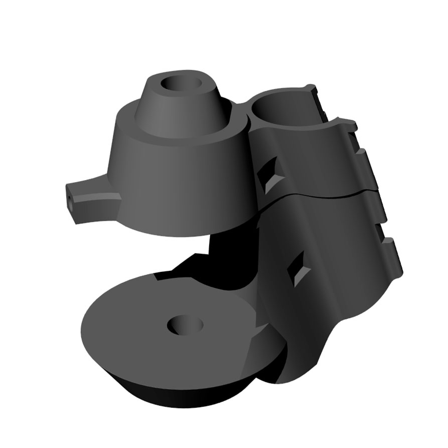
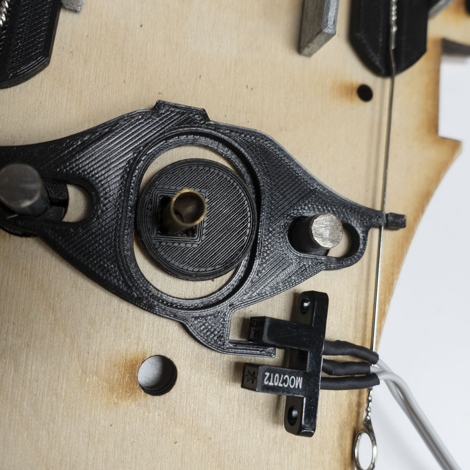
At this point, I really wanted a way to tell which position each of the cams is in, so on power up the loom would be able to scan though and check the physical state of the loom. Up until this point, I’d just been leaving the loom in a known state or manually adjusting the cams to that state, and that was a drag. Thankfully I’d put a IR gap sensor leg on each of the cam followers. When the cam was fully forward, the IR sensor would not be blocked, but when the cam was all the way back the IR sensor would be fully blocked. The IR gap sensor moved around with the cam driver, so it always knows about the current cam follower position. This made it easy to write some code to scan though all the cam positions and read the state of all the followers. This really reduced the startup time on the loom if I had left it in some random cam state on power off.

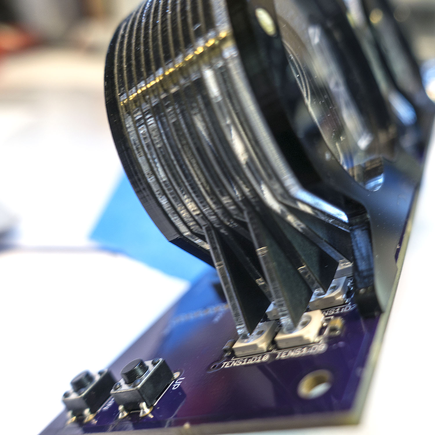
In order to view the IR sensor output directly, I added a way to poll it over bluetooth so I could see a kind of chart recorder output from the sensor. This made it easier to set the various thresholds and also see how much noise was in the signal.

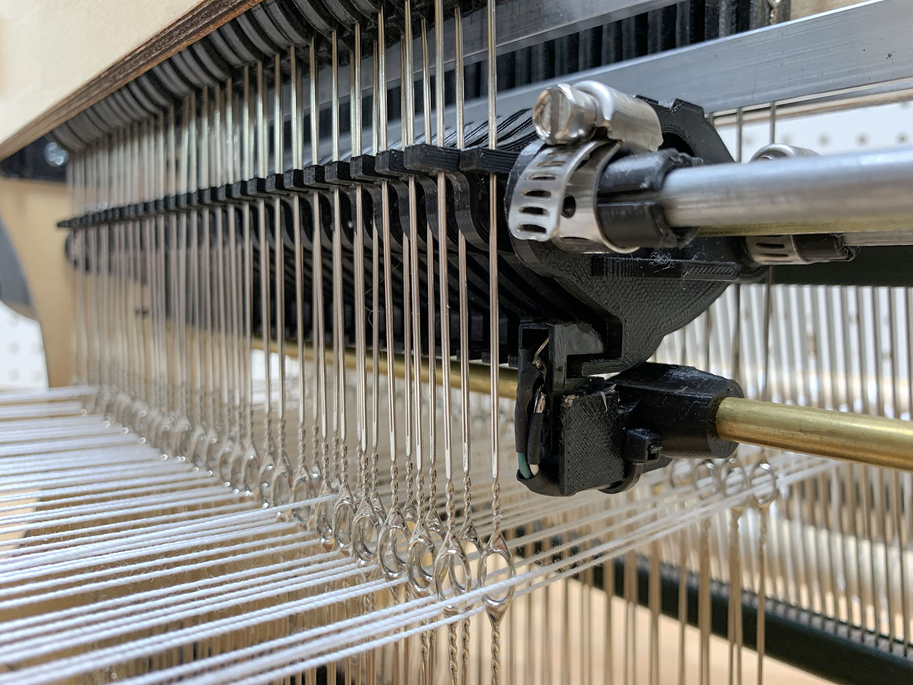
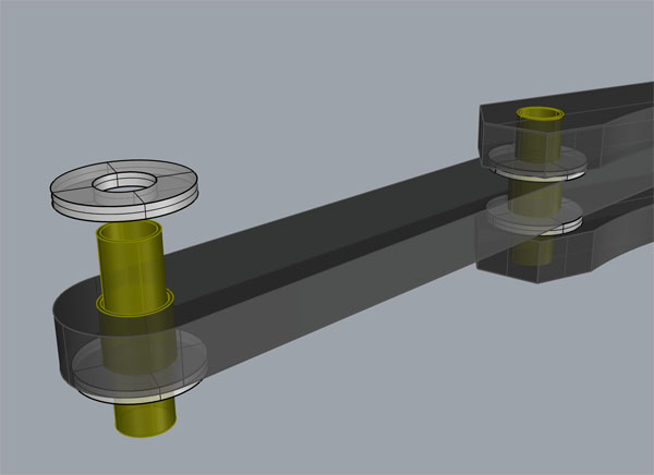
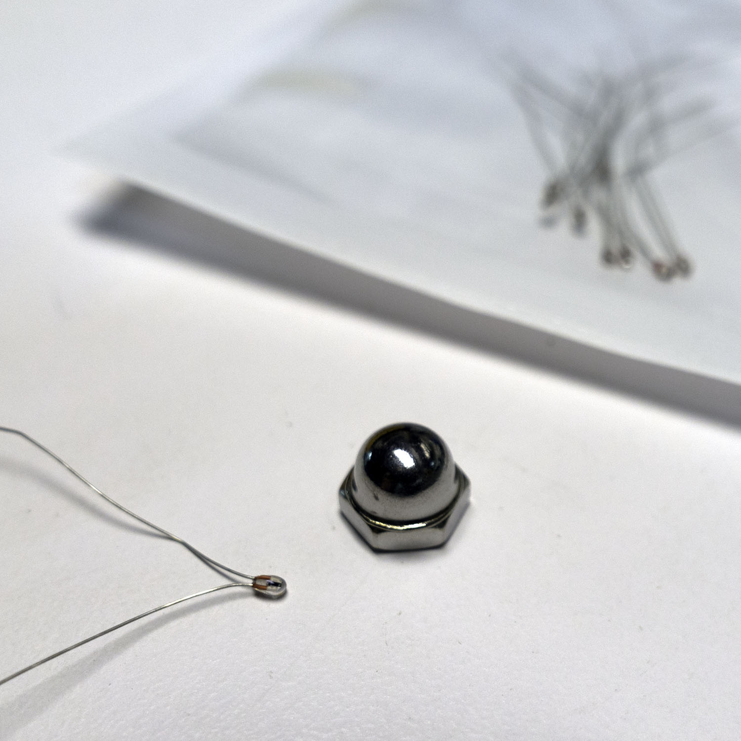
IR Sensor reading a cam position. The wires for the sensor run inside that brass tube.

How do you deal with positioning if the cams are not all identical?

At first, I thought I could scan for the cam positions using the IR sensor I’d added that detects cam positions.In theory that might work, but sadly because the cam followers are thin enough to not rub against one another and float a bit on the cams, there’s a lot of noise in the exact positions relative to the cams.  So scanning their positions was not really the silver bullet I’d hoped for.  Thankfully I had another idea. I could number all the cams then assemble the loom with JUST the cams. Then I used my phone to manually seek the positioner section to the center of every 10th cam. I wrote down those values and wrote some interpolation software that would compute cam positions interpolating between those values. This caps the interpolation error. It’s almost like having six 10-cam looms lined up. Then you just have to re-assemble the loom with the cams in the same order. This was somewhat annoying to do, but it totally worked, and I was back in business.

The hardest part?  The On/Off switch.

After the loom was no longer jamming, I worked on redesigning the PCB and making an integrated enclosure. The problem was that the original board had been designed for something that was never going to be turned off, so it used 2 power supplies and had no support for an on/off switch. When I designed the board, I decided I wanted to simplify down to a single high current 19v laptop supply and used a buck converter to generate the 5v needed for the LEDs/electronics. However, my initial choice of using an ACT4088 was a bad plan. It didn’t have great application notes, and my initial stab at layout caused some sort of power on spike that was killing all the downstream electronics. I blew up a number of those chips and even contacted some folks online who’d used them in their projects only to find out they’d had troubles with them too, especially when operating above 12v.  Clearly, I was trying to be too clever, and this was not working. I decided to make that piece of the design someone else’s problem by using a 3-pin switching regulator. I switched to the $3  VX7805-500 and got a whole new version of the PCB made.  (V3 at this point)

This seemed to work, but eventually the board would die on power up. Some sort of power on transient that was still killing my boards dead. This is kind of the worst way to die since you think it’s working, fully populate the board, and think you’re done, then it eventually dies and takes $40 of other components with it. At this point I very nearly gave up, but then at the very end I decided to try again with a somewhat more expensive Traco Power TSR 1-2450 three-pin regulator. I also tacked in a 5.6 zener to try and add some protection to the 5v rail and soldered a 10uf filter cap across the BTLE daughter board since that was the only daughter board that didn’t have its own decoupling cap. This seems to have worked. At least, the most recent build of the board has survived a zillion turn ons now, so I’m going to declare it working.  *knock wood*

Frankly, this version of the board is kind of crazy since it actually has the cam motor shaft passing through the board, and it uses a lot of space for a 3rd stepper motor controller that I never populate/don’t expect to populate after giving up on trying to calibrate in a second cam moving motor. So the board really should be shrunk down quite a bit, but it was fun making it fit the enclosure, etc.

One last try

I decided to warp the loom one last time and try once again to weave at 60 threads, and it finally worked without jamming. I could probably go a tiny bit higher on the thread count, but I punted on my original design plan of two cam movers since I was having enough trouble with getting one cam mover to not jam. This limited the range of travel/the total number of cams. It’s also good to have some free space on either side, so one can work in the guts of the loom if something goes wrong. I’ll probably stop at 60 instead of 80, since it’s slow enough as it is.

Video Mish-Mash

I deiced to video this project. However, I spent over a year making the loom and shooting video. During that time, I slowly got better at the video-making process, which means that the style and quality of the early videos is way worse than the later videos. This has made for a somewhat lumpy feeling for the final video. There are some sequences I’m very proud of, and others that I think are just horrible looking now. Oh well, it would be too much work to reshoot some of that stuff. It is what it is.

Where to now?

Well, I’m tempted to work on making the loom faster, but a year and a half is a long time to work on a project (for me). Most of my projects are < 6 months, so I may just move on. I would like to work on some error diffusion style weave dithering, maybe write some procedural weaving pattern stuff, but frankly I think all my friends, coworkers, and family have heard enough about weaving/looms to last a lifetime, so maybe I should work on something else.

I’ve open sourced all the designs and the code, but be warned these things are a dump of the design files/software as I made them. There are no instructions. It’s not the least bit cleaned up.  There may not even be super obvious names/labels, so trying to build a functioning loom from those files would be pretty difficult. I was barley able to get the thing to go, and I’m fairly meticulous when building these kinds of things. I’m relieved it worked. Still, if you’re interested in this kind of build, it might give you some inspiration and a place to see what others have done.  I’m kind of surprised there aren’t more of these things around. The ability to weave crazy designs is pretty awesome.


DIY Fortnite Double Helix Costume

This year I scratch-built a Double Helix costume for my 11-year-old son Simon.  This was a bit tricky because the character was only released on Oct 5th, so reference art was a bit thin on the ground.  I did a combination of an original pattern for sewing the jacket plus 3D printing of the goggles, breathing apparatus, and bullets. With such a new character, I knew Simon was going to spend a lot of time explaining whom he was dressed as, but on the plus side he wasn’t going to run into any other kids with the same costume!

To make the head gear more comfortable to wear, I bought a cheap magnifier that had an adjustable head band and adapted the design to fit that.  That way it could fit different people and be flipped up out of the way so he could actually see out of both eyes.  I knew that he wouldn’t be able to wear it though a long night of trick-or-treating, but it would be reasonable to wear for modest periods of time.

First I sketched curves over the front/side views of the character and used those to model the front plate.


Then I extruded the outer edge and improvised a rim/nose cutout.  I looked at an old pair of ski goggles for basic angles and sizes.

I sanded and spray painted the parts, then did a round of aging/dry brushing to make the whole rig look a bit more worn and used.  Finally I added a lens retaining ring and a single red lens cut from a cheap pair of John-Lennon-style sun glasses.

I was going to add two smaller lenses and red LEDs to the smaller face projections, but the jacket ended up being quite complicated to design and it ate up the remaining time.

I also modeled the breathing apparatus and the big black bullets that go on his shoulder strap. The bullets were super easy and I ended up just using them “as printed” since they were already shiny black and the amount of time I’d have to spend sanding/painting them to make them perfect glass shiny black just didn’t fit my time budget.

Getting the proper fit for the mouth parts turned out to be hard. I added some adjustable pieces that mounted the jaw parts to the headband. They were quick to print and made it so I could quickly try out different positions on Simon’s face. No kid wants something directly over his mouth on Halloween! I made the mouth-covering parts quite a bit smaller than in the reference picture, but It still ended up being pretty heavy and uncomfortable. It was a good thing they were easy to remove. I was never really happy with the way it looked, but it was time to move on.

I started working on the patterns for the jacket/shoulder belt on the Saturday 4 days before Halloween.  I’d already gotten the material, and I was ready to crank, crank, crank.  I set up two sewing machines to cut down on thread/foot swaps.  I even took a vacation day on Monday so I could really just focus for three solid days.

First up was the ammo shoulder belt.

I used 1″ white elastic and some faux leather plus a 3D printed buckle. I could have made the elastic a bit tighter, but I was worried the belt would be trying to curl away from the shoulder mount. I made the fit just a bit snug and secured each of the bullets with a drop of hot glue. They never fell out so I guess that was good enough. I did eventually file the points off the bullets. Having such sharp things mounted on your shoulder would be a real hazard.

I put Velcro on the underside to mate with some on the shoulder of the jacket. That way it could be removed easily but wouldn’t keep slipping off his shoulder.

I experimented with using painter’s tape instead of pins for the faux leather.  It worked fine, but it was annoying to remove in areas where I’d accidentally sewn though it, so I decided to revert back to pins. The extra pin holes are pretty invisible in the black grain of the faux leather, and it wasn’t saving me any time.

Next came the jacket pattern design.

I spent a full day with scotch tape and butcher’s paper tweaking the shape and design of the jacket. It was nice to be doing it during the weekend since Simon was available for testing the shape and size of things. He was a trouper putting up with me making pencil marks on paper he was wearing which was pretty tickle-y.

When Simon wasn’t around I didn’t have a dressmaker’s dummy, so  I made due. I stuck a snake’s head on a lamp.  Hey, I’m not proud.

It was at this point that I started to realize how tricky the asymmetrical design of the jacket was. On the original character’s jacket, most of the panels were made up of many sub panels.  I simplified it down some.

Then it was on to cutting out and piecing together. I had never done the kind of elastic cuffs that this jacket required. They almost didn’t fit on my sewing machine and having to switch between white and red thread was a pain, but they came out super nice looking.  I’ll never look at an elastic cuff the same way again.

The faux suede I was using was somewhat annoying to pin. I do everything with pins. I also discovered that it was a bit too thin to hold the hood shape well, so I did a felt backing for all the pieces in the hood. That worked, but kind of killed the time I’d budgeted to put a satin liner in the hood and collar.  So unfortunately the guts of the hood/collar are visible while he’s wearing the costume.

After a day and a half of pinning and piecing, I finally had the jacket mostly done, but did not have the time to build some of the extra sub paneling I’d been hoping to do. I had thought maybe I could just sew some lines on to show the pattern of the panels at least, but the unbacked faux suede was prone to forming small puckers along the sewing lines that made lines not look that clean. I just punted.

I did sew pattern lines onto the shoulder pads since the reference art showed there was a pattern there.


I’m happy with the way the costume turned out. Simon liked it too. In retrospect, I should probably have 3D printed the elbow pads for the character because they would have been very easy to do, but they wouldn’t have been that comfortable and they would have cluttered up the look. Halloween is SO FUN.  I love having and excuse to do sewing projects.

Make Yourself More Precise

I’ve invented a new and exciting way to probe circuits more precisely. An old idea used in a new context. After using it, I can say it is a must for any electronics bench. What is it?

I have been building electronic circuits for a long time, but only in the last few years have I gone all-in with itty-bitty surface-mount parts. I built a reflow oven. I got a stereo microscope so I could see what I was doing, and I practiced soldering and reworking under the scope. I was surprised to discover that for many operations using surface-mount components was faster and easier than using through-hole packages. Why hadn’t I switched earlier?!

The one part that was getting harder was troubleshooting the boards.

 I had a board with a chip in a little QFN 28 package, and each pad was only 0.25 mm wide. The board wasn’t working. I really needed to figure out what was going wrong, but some of the important traces didn’t go though any exposed areas except at those tiny pads. How the heck was I going to probe this thing?

If I just went in with a scope probe, I was certain to short something out. I just don’t have a steady enough hand to poke around with sub 0.25 mm precision. That’s when it hit me. Engravers use something called a Pantographic Engraver to put the tiny lettering on wedding rings. Could I make some sort of Pantographic Probe to let me probe around the circuit willy-nilly with crazy precision? Yes. Yes, I could. That’s how the Pantoprobe was born.

You can build a Pantoprobe for < $20 if you have access to a 3D printer and a few hand tools.  The project has even been featured on Hack-a-Day and Makezine!
I hastily modeled a basic pantographic mechanism to 3D print. The one tricky part about a pantographic mechanism is that the joints have to have very little slop or stiction. I decided to use telescoping brass tubing at the hinge of each joint, with a pair of washers reducing vertical slope. I used a camera ball joint (that I had sitting around) as the base. This ball joint also lets you tilt the probe at different angles, providing an extra degree of freedom that most pantographs don’t have.

I printed a few test joints. The joint design seemed to work very smoothly, and I was ready to give the full assembly a try. What to use as the actual probe? I had some spring steel piano wire around, so I crimped a bit into another piece of tubing, ground a tapered pad on the end, and stuck the whole thing through the center of the pantograph’s output joint. That plus an alligator clip and it was time to take the probe for a test drive. Would it work?

I was amazed to discover that not only could I reliably place the probe on the center of the solder pigtail of those .25mm pads, but I could feel the probe pressing into the solder. Crazy! That tactile feedback really makes it nice to use. The contact is more than stable enough for me to look away long enough to read the oscilloscope/multi meter. Trouble shooting tiny boards will never be the same!

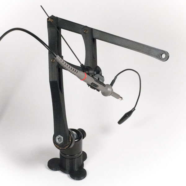
I did some more designs to make the probe fold up more tightly so it could fit in my pack of trouble-shooting widgets. I also ordered some cheap ball joints from China since it seemed like I’d be making more of these things. The probe was a HUGE win: Cheap, not that hard to build, makes the impossible possible. What else could I do with this idea?

I could already do Pick and Place with tweezers, and it wasn’t a big problem. I had some parts sitting around for building a suction pick and place tool, but I’d never gotten around to building it because, hell, I could just do it with tweezers. What if I gave the Pantoprobe an extra-precise rotational axis and plumbed a suction tip into it? Would that be awesome? So I built this Pantographic Pick and Place device.

Now THAT looks like a actual mad science invention. I used two o-rings to act as drive belts for an index-finger controlled rotational axis. The suction comes in via a pivot that then passes though the pantographs output axis and comes out to a syringe with swappable tips. Here you can see a small green tip holding an 0603 resistor. This was a bit more complicated to design.

My 3D printer really got a workout. I printed 7 different versions of just the hose clip! I went crazy and even designed a box to hold all the tips. In the end, it works, it’s nice, but it doesn’t have quite the super high return on investment that the Pantoprobe has. It’s only two 0-rings and a syringe kit more expensive to build than the Pantoprobe. As long as you already have some system to provide suction.

If you do a lot of pick and place and would like a steadier hand, you should build one. But it doesn’t make the impossible possible like the Pantoprobe. That’s the real killer app.

What else?

I realized that for measuring high frequency stuff the Kurt’s-random-piece-of-piano-wire sure left a lot to be desired. Maybe I could make a scope probe holder for the Pantoprobe?

The scope probe was going to have to stick out at an angle so I could still see the end under the microscope. Because it would stick out a long way from the axis, I had to worry about rotational slop. So I designed this rod that slides from the output joint though the opposite joint to lock rotation. At first I thought of this as just an insert that pops into a stock Pantoprobe, but as I struggled to keep the probe from twisting/flexing, I realized I was going to need to do something that attached both at the top and bottom of the joint. I printed it in two pieces and glued them together, and I also glued them to the shaft that goes though the joint. There’s no removing that thing. I added two zip tie ports so the probe could be fully locked in if need be.

Did it work? Sort of. Through my microscope I can’t see the actual tip, so you have to kind of think “the tip is right below the arc that is the side of the probe,” which kind of sucks. It wouldn’t be a problem if you’re just using an Opto-Visor instead of a scope. I also eventually figured out that my “clever” bar and tilted probe arrangement was reducing the precision multiplier of the pantograph, to something like 2x.

That plus the greater flex from the long probe extension makes the system less ridgid. It works, but the confidence factor/feel are not as good. Sometimes things slip. Another round of design on this one could make it stiffer and also increase the precision multiplier. I’ll have to see. This one is still very much a work in progress.

Maybe it would be smarter to make the piano wire probe into a more real probe in some way? Using 10:1 resistor divider and some coax cable, etc.

What else?

I thought maybe I could lock down the base so it’s easier to probe one handed. The great thing about using a 1/4-20 mounting nut is that I can use any sort of cheap camera mount. Luckily I’d ordered a suction cup mount when I’d gotten the ball mounts, so I was ready to give it a try.

The bad news is it’s hard to get your board in close enough with all those suction cups taking up space. The good news is that one-handed operation is reasonable with this setup. Two-handed usage makes it easier to hop large distances, and feels a bit more fluid but one-handed works.

I tried using my Third Hand to hold the probe locked on some test point, but it was infuriating. It really just didn’t work at all. Trying to position it was a mystery of over shooting and undershooting. A true fail. I was beginning to think maybe a fully locked test point wasn’t going to be a thing I’d be able to do. Then I realized I was over thinking the problem. I discovered that with a bit of technique you could lock the ball joint with the probe just a bit above where you wanted it, and then you could position it and the weight of the probe would hold it in place. Woot! Now you don’t exactly want to dribble a basket ball next to the “locked” probe, but it’s better than “you can’t do that,” and for bigger/safer test targets like a via I’d say it is safe enough. Still the rig is kind of huge. Maybe a smaller suction cup base would make it a lot better.

What’s next? Maybe an Exact-O blade tip for cutting traces? A higher precision multiplier one for people with shaky hands? A Dremel tool holding one? A soldering iron one? I think there are a lot of other good ideas hovering around this one. Build yourself a Pantoprobe. Give it a try. You won’t regret it!

Where do you go from here?

I feel like this is an important invention. Looking around, I didn’t see anyone making a product like this which is kind of crazy.   So I’ve done a lot of work to get the word out. I have the basic PantoProbe models on github. I made a video explaining the probe and another showing you how to  assemble one.  I set up pantoprobe.com to have a central place to point people, and where people can share ideas.

After building quite a few of these probes I also realized that there should be a simpler version of the probe that doesn’t have the complicated joints.  A very simple flexure based model.  So I developed the PantoFlex.  It doesn’t have the same range of motion as a full on probe, but it is almost trivial to print and use.  I also make it come apart so it could be printed on some of the smaller 3D Printers.

PantoFlexParts

Get out there and try one!


Laser Cutter Tips and Tricks

  • Do designs in alignment, but then break up all the objects into “cut sheet” layers organized by the material they need to be cut from.
  • Do design in exact dimensions without kerf compensation, those tiny .002 changes are nearly invisible and will drive you crazy. “Did I already compensate that?” I only every apply the compensation to a copy of a single layer I’m going to cut and then save it out as a ToCut version of just that layer.
  • Design with groupings for easy editing, but collapse parts down into individual compound paths using the path finder when you are making your cut sheets. This helps offset paths do the right thing for kerf compensation.  If everything comes out right, but you have a few holes that are way to large, you forgot to collapse them, and the kerf compensation made them bigger instead of smaller.
  • Control Cut OrderControl Cut order.  If you’re cutting open paths or have closed paths that overlap the normal “inside before outside” cut ordering won’t apply if you care about cut ordering organize the parts into separate cut passes.
  • Look out for exactly duplicate paths hidden on top of one another. That causes double cut problems. Find them by zooming way out so the anti-aliasing makes the overlapping ones appear darker.
  • Do Not Put Parts Too Close TogetherAvoid paths that are too close together.  The thin sliver of material won’t be able to dissipate the heat as well as a wider section and may melt or burn.
  • Use tape to hold pieces in so the excess material forms it’s own parts organizer.  You’ve already carefully laid these things out in an nice sheet, why not take advantage of that?
  • Use 3 ring binder sleeves to hold on to thin sheets of organized parts. If you’re using the tape and excess material trick above, if you limit yourself to 8.5″x11″ sheets of thin material you can orgnize a zillion sheets in one three ring binder.   Just be careful not to pick it up upside-down.
  • Use pulse rate to control edge properties lower on wood for a less chared edge. Higher on plastic for smoother finish.
  • Remove uneven protective coatings.  If cutting pastic with an uneven or bubbled protective sheet of plastic on top peal it away first to get more consistent cuts.
  •  minimizeRasterDistance raster areas into blocks to minimize the raster span.  When raterizing the laser goes back and forth over and over. The shorter the distance it has to go the quicker the raster progresses.  Clumping your raster parts can really cut down on the amount of time spent waiting.
  • Pay Attention To Grain DirectionPay attention to the grain orientation on wooden parts.  It’s important visually and also important structurally.  It’s not as important for plywood.
  • Use char artifacts to you advantage.  When laser cutting wood the compressed air blast adds a charred “cut shadow” on the upper surface, you can orient parts to take advantage of this, by making that shading part of the design.
  • Do small test cuts with a particular laser and material before deciding on the settings for a long set of cuts. I usually use some 1/4″ circles in a scrap area of the design.
  • On wood go a bit slower than your test cuts indicated. Wood is not a uniform material go slower/use more power than the minimum you needed for your small test cuts so as not to leave a few tough areas uncut at the bottom that you’ll need to cut loose and touch up.
  • Push Parts Out In Correct DirectionPush not-fully-cut wooden parts toward the bottom.  If the wooden part very nearly cut though and you’re able to just push the parts free, pushing on the top of the part makes sure that any splinters that pull free at the uncut areas pull free from the scrap around the part.  If you push the other direction the splinters come off your part, and ruin it.
  • Use a wood burning pencil to hide hand cut edges.  If you have to cut some wood loose, trim splinters, or sand down some edge it will leave unburnt bright wood in the otherwise evenly burnt edge.   You can shade these areas in with a wood burning pencil or cheap soldering iron so they mostly disappear.
  • Don’t make everything a rectangle.  Part of the lasers power is awesome curve cutting. Don’t make everything a rectangle. Add some curves. Not everything has to be 90 deg or a strait line.  Do not assume everything is a box.
  • Use Scrap To Form Clamping JigUse the scrap around a cut piece to form a handy clamping  jig.  If you use complex shapes they can be hard to clamp for gluing.  The scrap material around your part fits it like a glove and a few extra cut lines can make that come free and you can use it to hold your part in a clamp while gluing.
  • If  your forming a box edge with mating fingers don’t use alternating squares.  Work joins into your design.  Make a nicer more intentional patterns.
  • HideTabs Under Other ObjectsHide slot an tab connections if you can.  Sometimes you need some tabs and slots to hold on a part, and you haven’t been able to make the tabs fun enough to work into your design, you can do other things to deal with them.   You can hide them under glued on decoration or reinforcement pieces, you can position them under other attaching pieces.  You can laser etch transitions to make them more interesting than just a weird rectangles.  Jazz it up.
  • Use an alignment jig to force holes and pins to be plumb.   Just because a pin joins two pieces don’t assume that the pin is plumb, the conical cutting of the laser means there’s nothing forcing it to be plumb. For 1/8″ pins I use a drill press to make a 1/8 plumb hole in a piece of wood, and put a stub of 1/8″ rod in that hole. Now if you stack two pices on the rod and down onto the surface they’ll be reasonablly plumb and you can glue them.
  • Use the protective paper on acrylic as a paint mask.  If you laser etch into acrylic though the protective paper, the remaining paper makes an awesome paint mask.  If you don’t need super alignment between the raster and vector cuts you can even do the raster pass first, paint, and then do the vector pass. That lets you paint the whole sheet willy nilly without having to worry about getting paint down in the cuts, or having to paint individual little pieces.  Take care to use some extra power/slowness to fully etch though the paper and into the plastic.  If you “only just barely” etch though you can have sticky residue from the paper still on the plastic and that is real pain to remove.
  • It takes more power/takes longer to cut/etch though plastic that has the paper on VS not. (and it’s different for paper/plastic protective layers)
  • If you’re cutting lots of small plastic parts consider pealing the protective paper away first.  If you don’t need a super pristine surface finish free of any slight fogging near the cut lines it’s way easier to just peal the protective paper/plastic away before you cut.  It’s a time sink peal it off a zillion tiny parts individually.
  • Cut Out Unused Sections for ReuseUse extra cut lines to separate and save unused areas.   When you lay out parts for cutting, you often have some areas that are not used.  If you add some extra cut lines to cut those ares into their own rectangles.   It’ is much easier to re-use that material and it’s much more compact to store.  Trying to hit some good areas in a big sheet full of holes is hard and a waste of your time.
  • Cut fancy paper weights. If you’re cutting very thin things like paper it will often just blow away while you’re cutting it because of all the air motion in the machine.   If you take a wood or plastic sheet and cut out a part just inside/outside the lines you’re cutting in the paper the sheet can form a curve hugging paper weight for both the inside and outside of the cut.  With those pieces in place while you cut the paper stays put.
  • Use tabs to hold paper shapes in place. Paper parts can blow away so put gaps in the cut edges to keep them in place. Position the tabs where it will be easy to trim them (avoid corners or curves)  Cutting the gaps screws up the lasers inside/outside cut ordering so use explicit layers to control ordering. You can get away with a single tab if you put it “upwind” of the direction the compressed air on the laser will be blowing.
  • Make a paper clamp. If you want to cut a lot of sheets of paper all at once you can use the “fancy paper weight” idea but use 1/4-20 bolts and wing nuts to make a clamp to hold the paper together as a single chunk. (be on the lookout for fire though!)  I did this to cut secret compartments out of books.  It works but is messy and kind of a pain.
  • Use the mechanical properties of your material. Thin areas can be used to add springiness  Keep in mind that sharp corners and nicks can concentrate stress.
  • Cut some extras. It’s always a trade off between cutting time and output, but if your project needs 5 of something consider cut 6 or 7 of them. If they’re tiny or easily broken cut more.
  • Look for the flash. If you want to know if the laser is compeletly cutthing though your material, look for the flash as the laser hits the honeycomb support below the material.  If there are no flashes then you’re not getting all the way though.   This is easier to see with acrylic, not so easy to see with wood, etc.
  • Remove Inside CornersFor 90 deg braces cut out the inside corners.  If you are added braces to hold other pieces in alignment, and they’re just a tiny bit off the inside corner of the brace will push the brace away and spoil the glue bond.  Removing the inside corner makes the glue up more forgiving and makes for stronger joints.
  • Use water to deal with bowed wood.  Often with a sheet of plywood it will be somewhat cupped.  Instead of trying to fight that with weights you can use a paper towel and water to moisten the concave side.   In a couple of minutes the water will make that side of the wood expand and flatten out the wood.  I’ve used this to great effect on 1/4″ plywood.
  • Use water to protect thin sections on multi pass cuts.  In wood it’s easy to have thin sharp angled features char badly on the second pass.  Between passes use a syringe to put a tiny amount of water into the groove at these points.  The water will soak into the walls and keep them from charing as badly on the next pass.
  • Etch an alignment aid.  Want to laser etch consistently at a specific location on an uneven shape?  Etch an alignment sheet with the outline of the foot of the shape and use that to position the parts.   If you etch the alignment sheet deep enough it can even positively position the part since it’s footprint will click into the etched depression.  You can even use a flat bed scanner to figure out the footprint if it’s complicated.
  • Spiral cut to make deep pockets. Want to cut a deep pocket that doesn’t go all the way though? You can vector cut a tight spiral. You have to experiment with the specific material to get the right spacing. If you can try to etch from the center and spiral outward. Watch out for major heat build up.  Fire risk.
  • Be careful about versioning.  If you have a project witha lot of parts and your iteratively improving the parts take care not to mix versions of the parts.  It’s better to pitch old versions of the parts then to try and tell which ones have  modified slots that are 0.005″ narrower.
  • Check design orientation when cutting multiple passes in wood.  If you have long features where the laser moves in the same direction as the forced air at the cutting head that air will blow back along the cut fanning  any coals formed on the walls.  This makes the charing much worse. Try to orient the wood so the air blows across the grooves not along them.
  • Slow rasterization for dark details.  I used to always use max speed for rasterization, and adjust power to suit, but if you’d like to put dark details on wood it’s better to use lower power and slower speed to char dark details that are not deep.
  • Cut part way though to do kerf bending.  If you cut a lot of parallel lines most of the way though the material it makes the material much easier to bend.  If you are doing this in wood make sure to cut perpendicular to the grain so it doesn’t just split when you bend.

If you have other laser cutting tips put them in the comments!

Plexitube Owl Clock

owlTickAnimationSmallFor Christmas I designed and built six steam-punk owl clocks that have a novel faux Nixie Tube display. Nixie tubes are wonderful with their glass tube bodies and brightly glowing numerals, but think how wonderful a solid-state low-power any color “Nixie Tube” would be!

The basic idea is that you position an LED at the edge of a piece of acrylic that has a pattern laser-etched into its surface, and the LED lights up the pattern. Long ago I’d realized that a stack of 10 laser-etched digits with an LED to light up each digit might have the same visual charm as a Nixie Tube, and the Plexitube was born.

I’m pleased with the way the project turned out.  I’ve put the software, circuit designs, and illustrator files up on github. I even made a short video of one of the clocks in action.  The project has even gotten some attention from Hackaday and won this Reddit unconventional clock competition.  Thanks a lot guys!

owlEyeElementsBackAndForthSmall

At the time it was unclear if light bleed between the layers would make the digits hard to read, so I sat on the Plexitube idea for a long time waiting for a project that could use that kind of display.

Then I went to work at a new company, and I had to spend an entire day listening to benefits summaries and corporate on-boarding. To pass the time, I started to do some sketches of an owl made from only two pieces of wood. I used my Swiss army knife to cut my co-workers’ name tags into owl prototypes. I really liked the design, and I thought it would be perfect for an owl-shaped clock with Plexitube eyes. Would this be this year’s Christmas Project?

I can’t really start a Christmas Project until after the Halloween Costume builds are done, but this project couldn’t really take shape until I’d at least tested the viability of the Plexitube. I figured if I just spent one evening laser-etching a digit stack and holding it over an LED, I could figure out if the displays were going to be an unreadable mess. If it failed, I could pull the plug on the owl idea before they got out of the paper prototype stage. So I spent one of my Wednesday nights making a prototype stack.

VeryFirstTestOfPlexitubeThe prototype stack had a lot of issues. The back digits where hard to read, there was a lot of inter-digit light bleed. I really couldn’t say for sure whether this was going to work. That’s pretty much the worst-case scenario for a make-or-break prototype. Really, I should have just stopped then, but I couldn’t stop thinking about the nice owl shapes.

The Impossible Project

Halloween came and went and I needed to decide. I even went so far as to do some prototypes of an alternative project that was much simpler, but I could tell that the owls were the ones that wanted to be made. I’m usually pretty careful planning one of these projects, and never before had I taken on one that had so many BIG unknowns. I’d never worked with surface mount electronics, never bent wood to such small radii, never designed a PCB with a lot of exact physical layout constraints, and never used an in-circuit programmer. I decided to go for it, but I knew I’d have to get first-time-success-lucky on a number of things, and I told my coworkers that I did not expect to succeed.

Two months and counting

realTimeClocksTime to make a lot of quick choices and order stuff from China. I chose the popular Neopixel surface mount LED as my light source. They could be any color and all 40 of them could be controlled using just one pin from my controller. I decided to go with the ATMEGA328p, which is the same chip in an Arduino UNO. I was building 6 clocks, so I’d need 240 LEDs. I ordered a reel of 500 from China, along with some surface mount capacitor and resistor assortments, photo resistors, and some DS3231 real-time clock modules with battery backup. Ordering things from China is very cheap, but it can take a few weeks for the stuff to show up, so I had to get that moving quickly.

Now ordering printed circuit boards from OSH Park takes something like 10 days, so I really needed to get that in the pipe. If the first set of boards were a complete blowout, I could still get a second order in, but I had to hurry.

lightGuidesCloseupThe LEDs I was using are much fatter than that 1/16″ acrylic layers I was using, so each layer needed to have a sort of integrated light guide leg that would stick out and sit directly above the 3 tiny color chips inside the LED. The alignment had to be exact. So I measured an 10-layer alternating stack of acrylic and black card stock to get the exact spacing, and then I had enough info to begin laying out the PCB.


OwlClockPCBTopI used Eagle CAD and finally had to spring for the non-free version so I could work with more than one page of circuit. I had to use some tricks with the Grid to get all the LEDs laid out in the exact right locations. After a full weekend of fighting with Eagle, I had something I could send off to OSH Park. I also quickly ripped one eye segment out into another file and ordered 3 small “test boards,” so I wouldn’t have to do my first attempt at reflowing a surface mount board with one of my giant and owl boards.

Then it was back to working in Illustrator on the design for the acrylic digit layers, black card stock separators, etc. I customized the digits of a font to make them slimmer. All the digits obstruct one another, so I wanted something that was lovely, but was mostly empty space so other digits could shine though. I also did some tricks like make the zero (which is in the back) a bit bigger/bolder so it would still read well though all the other digits.

Secret Symbols

Now on a clock there are 4 digits, but not every digit needs all 10 numerals. Heck, the tens of hours digit only really needs a 1. That leaves 9 layers for other special non-digit things. I could, in theory, have put some extra digits in the back of the tens of minute digit since it only goes 0-5, but I decided if I was going to be showing other info in those lower digits, it would be better to have all the digits there. I also decided to keep the 2 in the hour-tens digit so I could support 24-hour time in the future, and show a full year like 2016, etc.

I wanted to show the phases of the moon, sunrise and sunset times, moon rise and moon set times, etc. I used 6 of my 8 free digits doing the arcs of the moon. Because all the layers are at different depths, I staggered them so the arcs actually make a 3D sphere shape with the middle most arcs at the front. That left me with 2 layers. I used one for a sun outline that could be used along with the arcs to show things like the equinoxes/solstices.

The Magic Eye

That left me with only one free layer, which I used to add the outline of an eye. I realized that the arcs could be used to animate a slit-pupil eye looking back and forth. Of course I needed that! My owls eyes have eyes?! Yes … yes they do.

Plexitube Assembly

eyeElementBeingStackedEach eye element can display two digits, and they are laboriously assembled by stacking 20 digit layers and 20 paper masks on 4 brass pins in careful sequence. Thankfully, the digit layers were fairly easy to keep track of because they already had digits etched into them! Each acrylic layer has to have its protective plastic peeled away, and its etching scraped and dusted. Because the pins are press-fit, I had to carefully push them down on the pins without cracking the 1/16″ acrylic. The first stack took me 2 hours to assemble. My finger nails were frayed from all the plastic peeling and I had 11 more elements to make. What had I gotten myself into?!

eyeElementBack

First Reflow

solderPasteStencilingFinally the owl boards came! I had also ordered a solder stencil from OSH Stencils. When making a board like this, the basic process is a bit like silk screen printing. You position the PCB under a stencil and squeegee solder paste though the stencil holes onto the board. Then you place all the itty-bitty components onto the board with tweezers. Finally you oh-so-carefully put the board in an oven and heat it up until the solder paste melts and the parts all snuggle down exactly into place via surface tension. A while ago, I had built a special computer-controlled toaster oven in order to do just this process, but I had never used it!

intoTheToasterI kept waiting for my test boards to show up, but eventually I gave up and decided to do my first reflow on one of my giant and indispensable owl boards. I populated the board, put it in the oven, and pushed the button. Then I held my breath as the oven went though its 3-minute cycle. Success! The board came out looking perfect! It looked like something totally commercial, not something I’d made with tweezers and a toaster oven. MAGIC! Surface mount is awesome. I’m never going back!

fiveOfSixBoardsForOwlsOk, so the board looked like it was all soldered up, but would it work? I hooked the LED chain on the board up to an Arduino UNO (remember how those NeoPixels can be driven by just 1 LED?) and some quick code showed that all the LEDs were working! I blinked each one red-green-blue to test and they passed with flying colors! *phew*

owlClockDigitTest54Now for the real question: would the digit display actually look good or was the whole thing going be two months of work for an unreadable mess? I wrote some code to cycle though the numbers and positioned the eye module over the LEDs. It sort of worked, but it wasn’t great.There was quite a bit of cross lighting between digits, especially between digits 1 and 2.

I was extra sad I’d left that 2 in the hour tens digit. No one wants to look at a clock and not be able to tell if it’s 11:14 or 22:14. Something really needed to be changed. But what? I did, however, decide to get my second round of PCBs made. OSH Park sends out 3x boards, so if I wanted 6 by Christmas, I’d have to order the second round pronto.

OwlLogo
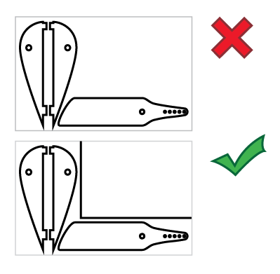
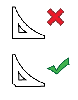
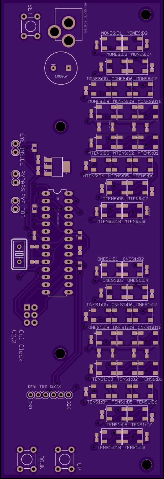
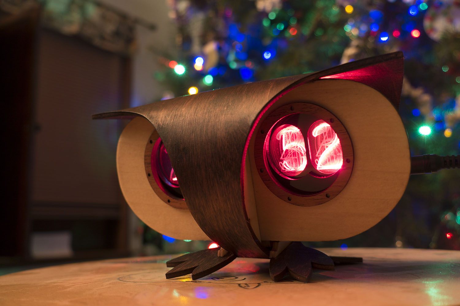
I spent an evening designing a nice owl icon to put on the second round of boards, added two regulator bypass pins, and then sent the thing off. No time for anything fancy. It turns out the icon was a fail.  Even though I followed OSH Park’s guide lines it did not render properly.


Eerie Is Good

plexitubeCloseupOne thing I did notice while I was running that test is that although the digits were not yet crystal clear, the whole thing had a very eerie feel to it. It was almost as if I couldn’t quite tell what the heck kind of technology I was looking at. It sure didn’t look like LEDs. The layers of acrylic have a wonder full “hall of mirrors” effect on the lit segments.  I also noticed that the light bleeding off the tops/sides of the eye element were kind of hypnotic to watch go through their sequence. I had originally planned to cover the elements with a ridged copper cylinder segment, which would have looked steam punk, but not as strange/cool as that bleeding light. I decided to leave them uncovered.

Back To Body Work

Now that the boards and the eye element design were mostly settled, I had to get back to figuring out how to design the bent body of the owl. I did a second pass of designing the body in cardboard. I knew that trying to bend 1/8 plywood into a loop maybe 3 inches in diameter was going to be tricky and might be impossible. In a recent build, I’d used laser “kerf bending” to make it easier to bend curves in thicker plywood. Could I take that to an extreme? MicroKerf Bending™? I tried spacing the kerf cuts .1″ apart, cutting almost all the way though the plywood. The results where a satisfyingly bendy piece of wood. Still the owl has some very wide sections at the top of his eye arches and those were still quite stiff. Too much variation to be able to bend into a loop.It would have been nice to write some sort of script that would space the kerfs closer/wider based on the overall width of the piece, but I had to settle for just doing a few different spacings by hand.

owlBrowClampThe brows above the eye were delaminating when I’d apply the bend. That was bad. I fixed it by pre-sanding the upper layer thin in those areas and by putting a few little spring clamps on those edges during the bend. That solved the problem, but all these iterations on the body design were burning up time at a crazy rate. Would I make the Christmas deadline!? Here I’d been thinking I was saving time by having most of the owl form come from just one piece. So wrong.

Steaming and Clamping

owlInClampingJigI built a clamping jig out of a big board and carved away clearance for the owl feet. I’d steam an owl body in a pot on the stove and then bend it with my gloved hands whilst racing out to the garage to clamp the body around the face in my special jig. The first time I did this the face of the owl split in two! Yes, when the body is looped back on itself and clipped tail to feet the forces on the face are nice and balanced, but while you’re bending that around the forces on the face are actually pretty big. So I changed my clamping jig so it would support the face during the bend. Finally, it worked!

boardInOwlTest
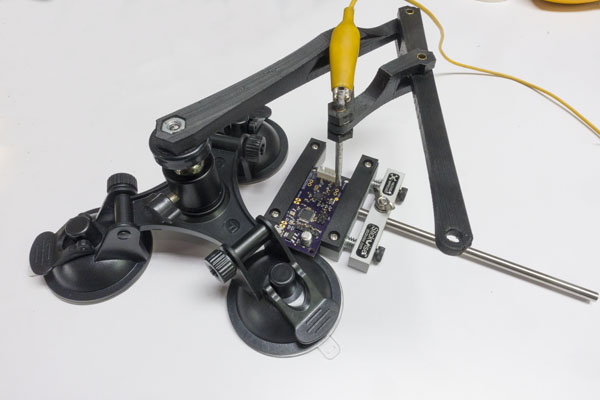
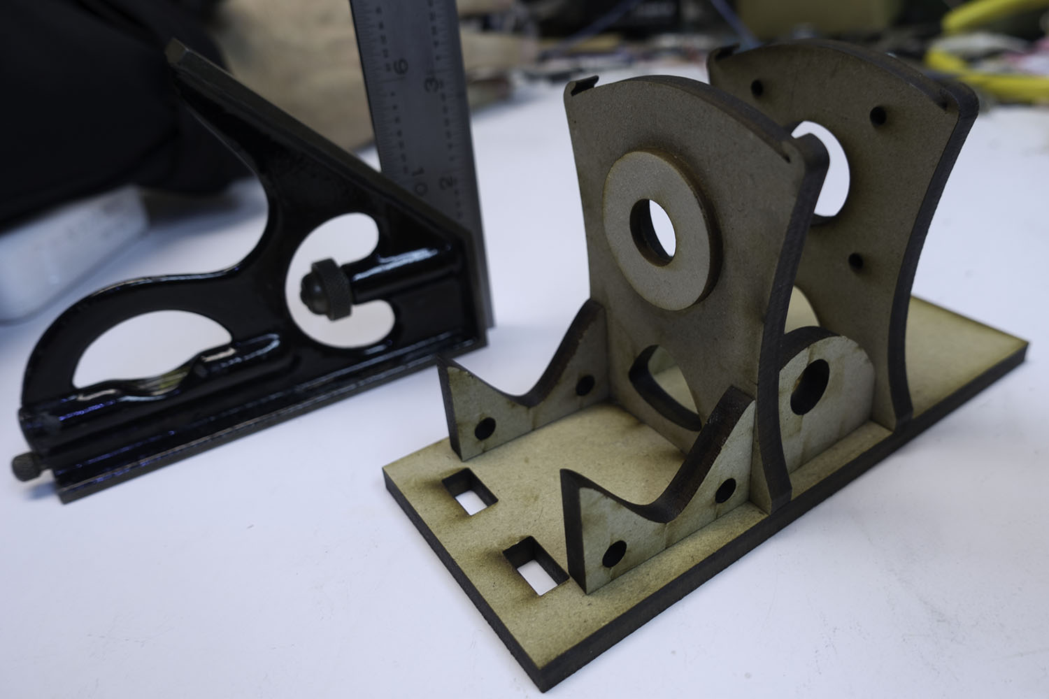
I had a lot of other little issues. I had to add some “foot prop” pieces so I could have a way of evening out feet after the main clamping was done. I thought I’d be able to adjust the owls stance by adjusting the tail angle, but a sort of scissoring action made it so any amount I pushed up the tail also pushed up the feet, canceling out the adjustment. So the owls look down a little bit more then I’d like. That’s okay though because they like to nest up high.

owlsOnTheClockFaceI wish I could have used 1/8″ mahogany plywood. Then I wouldn’t have had to deal with staining the outer body. However, that’s not something I can get locally so I was stuck with stain. I hate stain. I tired pre-staining, which gave nice crisp edges at the stain boundaries, but that made the gluing a lot weaker. I tried post staining with with pre-clear coating areas to try to reduce bleeding over, but it still bled some and required lots of awkward sanding to fix. If I had it to do again, I’d try to get hardwood ply. I did eventually get them all glued and stained.

The Secret Sauce

secritSauceUnderSideOfEyeI’d been thinking about my eye element problems. How could I improve the contrast? I already had black card stock all over the place blocking as much light as I could. I realized that as tight as the fit was around the card stock, there were still micro gaps, and the light leaks I was seeing were probably coming right up from the LEDs and into the clear bottoms of the other segments. I decided to use a small brush to paint some black acrylic into those areas! EUREKA! That fixed the problem entirely and now the displays looked great.

Christmas Eve

owlClockInFrontOfTreeIt was Christmas Eve, and I was still clear-coating owl bodies. Applying wood finish on Christmas Eve is par for the course for me. The big issue was that I was still driving the displays from a separate Arduino and hadn’t fired up the on-board computer at all. I spent a while reading about fuse bits and fighting with boot loaders, and fiddling with Arduino IDE config files. Had I made some mistake with as-yet-untested parts of the PCB? Could I get lucky one last time on this “impossible” project? Yes! At last, I was able to program the chip on the clock board, get the real time clock synced with Greenwich Mean Time, and put enough code in the clock that it could actually display the time! The clock could go under the tree.

Software in the New Year

Early on I had decided to punt on all but the most basic software until after Christmas. I had pages of ideas on fancy software features, and I knew I’d have enough trouble just getting the things physically built by Christmas. This was going to be a Christmas gift with an eventual “firmware upgrade” gift chaser.

owlSimulatorExplodedViewI knew there was going to be a lot of software, so I wrote a iPhone owl clock simulator to give me an easier platform to develop some of the code. I had been reading Jean Meesus’ Astronomical Algorithms, and I wanted to have the clock not only show the phases of the moon, but be able to display sunrise/set times and moon rise/set times.

I had included a light sensor on top of the clock so the clock could dim a bit when it was in the dark, but it could also tell if your hand waved over the clock and maybe then it would cycle though showing the sun going though sunrise colors while showing the sunrise time and the show the sunset time while cycle though the sunset colors.

Color Picking the Old Fashioned Way

colorPickerWithThreePotsAndUnoI really wanted to use nice colors in the clock, but just choosing 3 numbers for Red/Green/Blue doesn’t tell you what those are going to look like in the final display.  I needed a way to search for good colors.  So I made a super simple color picker by hot gluing three potentiometers to a board. I used an Arduino UNO to read the three RGB values and display the color on  a jury rigged LED + acrylic digit. Go Go gadget gaffer’s tape! The program would print the values out to the serial monitor.  That way I could find just the right pink by fiddling with the knobs and then write down that RGB triple from the screen.   I used that to make a whole pallet of colors I liked.

The Trouble With Doubles

The big problem was that most of the Astronomical Algorithms need double precision math. The solar system is big and you need the precision, but the Arduino tool chain doesn’t have real double precision math. I spent a while (stupidly) writing a math lib that did approximate double precision math using two single precision float values based on this paper targeted at GPU computation with floats. I did get the math working, but to my horror, I discovered that the code it produced to compute the equinoxes/solstices was so huge that it didn’t fit into the 32k of memory on the ATMeg328p. That was a huge waste of time. I did, however, use the code to generate the next 100 years of solstices and equinoxes and compress them down into just 100 bytes of Progmem, but the sunset/sunrise times were doomed. I went back to some still usable moon calculation code so the clock can show the current phase of the moon.

Then I wrote a lot of silly features. On the clock recipient’s birthday, it displays in their favorite colors. (And on their kids’ birthdays, their kid’s favorite color, etc)

I wrote all the code to set the time/date/gmt offset with nice auto repeat ramp ups and useful icons. (When you’re setting the month a sliver of moon shows, when you’re setting the day there’s a sun icon, etc) I even used the right arc of the circle to show AM and the left arc for PM like they were the first and second parts of a 24 hour clock face. Not that I expect people have to set the time/date much, but a clock needs to do that.

The clock counts down to midnight on New Year’s Eve and shows fireworks and a spinning golden globe at midnight. On JRR Tolkien’s birthday, the the eye of Sauron looks around and sometimes a golden ring spins and the digits are red and fade up and down like like a breathing beast.  etc.  I don’t want to give to many surprises away.

Needless to say, there are a year’s worth of Easter Eggs in the clock code, even on Easter.

Two Words “Optical Theremin”

photoresistorsWhen I was working on the auto-dimming feature, I wanted to have a direct readout of the light sensor, so I could fine tune a mass/spring system for the dimming rates. When I first hooked it up, I realized that with a much stiffer spring it was pretty neat to play with. You’d wave your hand over the clock and the digits would smoothly go up and down. It was kind of mesmerizing.

I was showing it to a friend, and when I started waving my hand around he said, “Wait, it has a Theremin too!?” and the Optical Theremin was born. I hooked that code up to the hue of an hsv conversion and now when you press the down button, you get one minute of “Optical Theremin” where waving your hands around changes the colors and numbers in a soothing and lovely display of Plexitube awesomeness.

It’s hard to stop writing code for the clock, but after the “Optical Theremin” feature, I started getting close to the memory limits and I decided to call it quits. It was time to give out festive springtime firmware upgrades! I had been trying super hard to have the code all done before the spring Daylight Savings Time change because people had clocks they couldn’t set! I only missed that deadline by a week. I blame double precision!

owlTrustBuidingExercise

Clarence was starting to think that perhaps this hazing ritual was going a bit too far…

Cutting 3D Shapes on a Laser Cutter

twoKnightsWhen my local TechShop got a 120-Watt Epilog Fusion laser cutter, I knew it was time to try out something new. Being able to cut though fairly thick material made me wonder if it was possible to cut out 3D objects with the laser. Most laser cutters produce 2D output. They either cut and etch sheets of material in X & Y, or they cut and etch cylindrical objects (drinking glasses, etc) by turning them with a rotary axis which replaces the Y motion. In the past, I’ve sometimes used an indexing jig to turn the object and make XY cutting passes at various angles. What if I automated this rotation? Could I produce a 3D object by rotating the object and cutting out various 2D silhouette profiles? The process is limited buy the max cutting thickness of the laser. You can’t hack an object out of a spinning 2″ rod of material if the max you can cut though is 1/4″.

The new 120-Watt laser seemed like it might be powerful enough make this idea practical.  I’d never seen anyone do this sort of work with a standard laser cutter. In industry, it’s common to add additional axes to cut at angles, but this XY plus rotational axis (A) was hard to google for. I liked the general shape of the project. At first, I could make a simple rotational jig and manually run a profile cuts though the laser just to see if there was any hope for the idea. If it seemed like it was possible, I could build a motorized A axis and use an optical sensor to sync it to the laser’s motion. From there, all sorts of interesting things could be done in the software to improve the output.

Hey we were featured on Hack-A-Day!

I find a partner in crime

I was pretty excited about the project, and I knew it was going to involve a fair amount of software and hardware. I wrote a super long email to my friend Lawrence pitching the idea. A few hours later he sent me an animated gif of a test model’s rotating silhouette. Clearly, he was in and already on the case! Woot! Lawrence and I have done a number of projects together, including the solar plotter project. He’s great to work with. I knew that with him on board, this project might really have some legs.
Right at this point, my TechShop announced that they were moving to a new location. The laser was going to be unavailable for a few weeks, so I decided to skip ahead and build a motorized A axis. This might’ve seemed overzealous. Why not do some tests with a manual jig first? Well, I was excited about the project and wanted to start building. As an added bonus, building the motorized version would get me to finally troubleshoot the PCB’s I’d designed for my motorized camera rig.

chuckAndShaftFiguring out what was wrong with that PCB would advance that project even if the laser project crashed and burned. So it wasn’t that big a risk to jump ahead, and I was VERY eager to get building. I ordered a cute little 3 jaw chuck so the motorized axis would be able to hold cylindrical stock of various sizes. The only down side to the chuck was that I’d have to machine a shaft with a very concentric 1mm thread. Not a big deal, but an additional hurdle for other folks wanting to build a rig like this.

I did write up that machining job, mostly so I’ll have something to refer to the next time I need to do single point threading.

DSC01277The rig is direct drive using a stepper motor, a zero backlash coupling, and two 608 skateboard bearings.  As Lawrence worked on a way to extract the silhouette profile curves and export them as .svg files, I worked on the most basic version of the device. I used an Arduino Nano and a little stepper motor controller all wired up a on protoboard with a button to advance 1/16th of a turn.
Chuck Stand Looks Like MonstersWhen TechShop reopened, I lasercut the rig to hold the motor, bearings, and chuck so I could glue it together. Lawrence had gotten his profile curve extraction code working, so we were finally ready to do a basic test of the idea.

twoButtonProtoboardInstead of having a fully automated cut-out in these initial tests, the idea was to export each of the profiles as their own print job. We could print them out manually pressing the advance 1/16 button between each file.

Here you can see our very hairy initial setup. The Arduino Nano is in red and the stepper driver in purple. Look Ma, no heat sink!

The First Night

FirstKnightSpinSmallOur initial test model was a chess knight. We started by chucking in a 3″ length of 1″ poplar dowel into the motorized chuck. We figured we could keep printing the same profile until we cut all the way though and then hit the advance button and move on to the next profile. One cut, 2 cuts, 3, 4, 5, 6, 7,8,9,10,11, finally it cut though. That was a lot of cuts. The wood was pretty charred. We knew the subsequent cuts would be quicker because of all the material removed by that first huge cut, so we continued on. Lawrence loaded, configured, and printed each of the profile cuts, and I opened up the laser, pressed the advance button, closed it back up, and fired off the next cut. Like a pair of bureaucratic button-pushing relay racers, we finally made it to the finish line. The results? The knight was pretty charred and battle scarred. His ears burnt entirely away, but he was recognizably a knight! We were jubilant.

The Second Night

Knight Focal Plane

One of the reasons the laser was taking so many passes was that the thick material had a lot of material far from the focal plane, and that meant more charring and less cutting from the laser.  We realized that although we couldn’t move the model vertically, we could have the focal point above the center of the model, and then by rotating 180 deg and cutting the mirror image of the profile we could effectively cut the same profile with the laser focus at two different levels.

knightSpinSmallSo I added a button to the rig that would rotate the model 180 deg. The first time we tried to cut the mirrored profile after 180 deg rotation, we discovered that the laser’s idea of the center of rotation was off from ours.  We needed to measure and adjust for the offset. After compensating for that, offset the idea worked. We once again did the tag-team cutting process, this time with a somewhat more complicated sequence of rotations that we checked off on a list. By the end of the night, we’d managed to cut out a less charred and scared knight! We even had some ear nubs! We were getting better step by step.

Can you use acrylic rod?

We did try this system on acrylic. Acrylic cuts very cleanly with no charring, and we thought it might have great results, but the process really depends on chunks of material being able to fall away. However, when slowly cut, thick acrylic has the tendency to melt just enough to make the chunks stick and not fall away. We decided to focus on wood for now, with the idea of revisiting acrylic at a later date.

Process Improvements

What were the next big steps? We realized that with better path planning, we could cut thin layers off the side of the rod in multiple passes to minimize the thickness we needed to cut at any one time. This spiraling-in process would allow us to cut each outline only once. We also wanted to add some cut lines to the outside edge of the material so the cut chunks would drop away more easily. Lawrence worked on those things, while I worked on building some sort of laser sensor so we could automate the rotary axis motions. Sitting around with a checklists pushing buttons was not a viable way to be doing this with ever-more-complicated cut sequences.

pcbWithRemoteI built a better two-button remote from some PVC, so we could at least not have to open the laser between passes. I also finally got around to troubleshooting the PCBs I’d had made for the camera motion rig. It turns out the Arduino Nano package I’d downloaded from the internet was for V2 of the Nano, but I had V3. For some unknown reason, they had reversed the order of the analog pins, which is a fatal change if you’re using most of the analog pins for digital IO.  Once I had that fixed in software, the board was only 1 oops wire away from being fully functional, so in an evening I was able to go from hairy protoboard to svelte PCB.

centeringJigI also made a centering jig that made it easy to put the rods into the chuck nicely centered. That way I could quickly chuck new rods without quite as much tapping and fiddling to get them to spin without a wobble. The next big improvement was a way to automatically advance the rig though its rotations as the laser went through its sequence. It would be so nice to be able to just hit “print” and have this system cut out a 3D model.

Blind to the Laser

My first inclination was to use some sort of IR photo transistor to watch the laser pulses and get a sense for when the laser was on versus off, and from there we could keep track of where we were in the sequence and when to advance. We could also in theory eventually use a sequence of laser flashes to communicate rotation sequence information to the rig. That way a single print job could handle everything. There was just one BIG problem with this idea, but thus far I was blind to it.

laserAndScope I built an ATTiny85-based pulse train detector and put it in the laser bed. No reaction. I tried some other random IR photodiodes/transistors I had around.  Still no dice. I hooked up a scope and saw zero evidence of the detector seeing the laser at all! I thought maybe the pulses were just so short that the system couldn’t see them, but then I did some more research. It turned out that the IR emitted by a big CO2 laser is totally out of the range of cheap IR phototransistors. In fact, room temperature versions of such devices had only recently become available and they were $800 used on eBay! Not an option for us. It’s counter intuitive that something so powerful that you can be blinded by even diffuse refection of its light can be entirely undetectable by cheap electronics, but there it was. I’d taken the project up a bind alley.

Acorn Nut Job

acornNutAndThermistorMy backup plan was to use a thermistor armored in a small acorn nut.  The reaction time would be quite slow, but it was simple. The acorn nut would protect the thermistor, and we could make the cutting sequence include having the laser blast the thermistor whenever the rotation rig was supposed to go to the next position. Hopefully, it wouldn’t get too hot over time.


acornNutAndPuttyI used a dab of heat-sinking compound on the tip of the thermistor and a glob of epoxy putty to turn the delicate glass thermistor into an armored frankensensor.  When I measured across the terminals to make sure I hadn’t shorted them out I noticed the thermistor value was drifting.   I was seeing the temperature rise of the epoxy setting!  So that was working.

This slow sensor did mean we were going to need a different way to load sequences into the rotation rig. There was no way a system like this was fast enough to communicate a sequence of angles. Luckily, I had another way of doing this. My motorized camera rig used Bluetooth LE to communicate wirelessly to an app on my phone. It’s only 9600 baud, but it works well and lets you have all a full-on user interface running on a device you already have in your pocket. Much better than my huge PVC-wired remote. Best of all, I had already written an app that scanned and connected to this kind of bluetooth device, so I was able to quickly hack that up into an app to control the rig. An iOS app isn’t really that open though, so I was kind of sad to be adding this particular step to our tool chain. I gave the app the ability to receive sequences via deep link.

The Biggest Problem

knightProfilesWe had, however, discovered a huge problem with our plan, a problem that was going to take weeks to resolve. I had been told by someone at TechShop that if you turned off “Smart Vector Sorting” in the lasers print dialog, the laser would output the vectors from back to front. Perfect! We could output SVG, import into Illustrator, and print it out. Sadly, that turned out to not be true. In fact, the order in which the vectors are cut out is entirely out of your control.   #%@$#! The vectors seem to be roughly y sorted and that’s that. God help you if you want to cut a zillion curves that are all in the same place. I exchanged emails with folks at Epilog with no real help. This is not exactly a big priority for folks using  a laser in its normal 2D capacity. For a little while, we worked around this by having one super long cut vector, but that was never going to work for models with holes, etc.

We noticed a project called Ctrl-Cut on Git Hub that was a third party laser control program for the Epilog Legend 36EXT.  Perhaps we could get it to work for the Fusion 120? I contacted Amir, and he was super helpful and generous with his time. I output various print files for him to look at, and he tried making a special cut of Ctrl-Cut for the Fusion 120 which would output the vectors in order. Progress was slow since I could only get on the laser one night a week. The printer files he was generating still had some issues and would crash the laser, which was pretty scary. Meanwhile, in the background, Lawrence was picking though the raw printer output and trying to get his path planning scripts to output the printers .prn files directly. Eventually, Lawrence was successful and he was able to generate .prn files, and we could  even change the speed and power settings between cuts in the same file. Awesome! For this, I hereby award Lawrence an honorary knighthood, and a special shout out to Amir for his help and ctrl-cut examples.

Raster mode awesomeness

knightWithTestRasterOne of the shortcomings of the system of cutting out a bunch of profiles is that you can’t get details that never appear on the silhouette edge of the model. Laser cutters have a “raster” mode where they sweep back and forth quickly and etch an image into the surface. The power of the laser at any point is modulated by the color of an input image. Because this is used to etch a bass relief, I knew it could be used to carve in details which were missed by the profile-cutting passes.

There were details I wanted to be able to faithfully reproduce in the wood, like the eye of the horse and the curve in behind the jaw. I hand drew a few details and tried applying them to the side of one our burnt knights.

To our surprise, the raster pass not only etched in the details, it also blasted away the surface material charred by the slower vector cutting passes. We realized that we may well be able to have entirely non-charred output by simply leaving a thin layer of extra wood on the surface and removing it later with a raster pass.


KnightHullRenderingrasterExample

I had a feeling we could use these raster adjustments to cut out a model very close to the shape of the original model. I really wanted to see that in action, so I learned a bit of Scene Kit and wrote a quick system that could draw all the laser cutting passes as geometry, and then fire rays though them to find the distance from the closest hull to the model. This distance controls the darkness of that pixel in the raster image, which in turn controls the amount of material removed by the laser. This was going to be great!

There was just one problem. On closer inspection of our knight model, I realized that it didn’t have much in the way of eye or nostril detail. They were just painted on in textures and not modeled into the surface at all! This fancy ray tracing system was going to be very useful with our not very detailed model. Not wanting to abandon the knight, I cast around for help. I don’t have much in the way of modeling chops, so I knew touching up our model was way beyond me. Having spent more that 8 years as an R&D developer at PDI Dreamworks, I had a few contacts who were up to the task. After asking around for help, Joshua West stepped up and entirely remodeled the knight for us! My Hero! So it was back to the races, armed with his slick new model. I used my rendering system to render out a Visual Hull To Model Offset Map or “Stripy Horse Picture.”

horseRightPass1Now we were talking! You can see how the inner ear, eye, mouth, and nostril are all represented. You can see how the raster is compensating for the faceting of the round base and the deep inset under the jaw, etc. I’d had this image in my head for months, and finally I had it rendered out where other people could see it. Now to see what happens when we apply it to one of our scorched and faceted knights.

Meanwhile, Lawrence had started porting his path planning code to a web app that turned out to be both much faster and more convenient than the python scrip we had been using. We were about to try a number of firsts all in one night. Our first fully automated cutting of the model with the thermal-switch advancing the rotary rig. Our first use of the new speedier web app for path planning and our first (admittedly hand aligned) attempt at fine tuning the model with a automatically generated raster pass.

We had a few false starts: I had to add even more averaging of the thermal sensor to smooth out motor noise that was causing false triggers, and Lawrence had to add back in the “burn a line on the thermal sensor” path segments which had gotten left behind in the port. We managed to get the thing cut out and rastered up, and I’ll be damned if it didn’t look pretty darn good!

firstRasterPassKnight improvedKnightModel

You can see the eye detail, nostril, the jaw line, even the inside of the ear came out! We were ecstatic. There it was, 3D model to wooden model in only a few minutes worth of laser time! The dark lines on the model are actually the places where the model wasn’t touched by the raster pass. Kind of the negative of the dark lines in my rendering. I think, with the addition of a small amount of protective material left on for the raster pass to remove, we should be able to have a mostly-not-burnt looking knight.

We were so excited that we cut out another one, and when that came out we decided to go for broke and cut out a long DNA-shaped helix model. It was our first attempt at a model other than the knight. It was looking pretty neat, but near the end the thermal sensor missed one of the rotation signals. The final pass cut the twisted ladder away, rung by rung, until there was nothing left.  Oops.

If you’d like to see the code, and the PCB designs you can check them out on github.