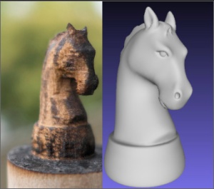
 When my local TechShop got a 120-Watt Epilog Fusion laser cutter, I knew it was time to try out something new. Being able to cut though fairly thick material made me wonder if it was possible to cut out 3D objects with the laser. Most laser cutters produce 2D output. They either cut and etch sheets of material in X & Y, or they cut and etch cylindrical objects (drinking glasses, etc) by turning them with a rotary axis which replaces the Y motion. In the past, I’ve sometimes used an indexing jig to turn the object and make XY cutting passes at various angles. What if I automated this rotation? Could I produce a 3D object by rotating the object and cutting out various 2D silhouette profiles? The process is limited buy the max cutting thickness of the laser. You can’t hack an object out of a spinning 2″ rod of material if the max you can cut though is 1/4″.
The new 120-Watt laser seemed like it might be powerful enough make this idea practical. I’d never seen anyone do this sort of work with a standard laser cutter. In industry, it’s common to add additional axes to cut at angles, but this XY plus rotational axis (A) was hard to google for. I liked the general shape of the project. At first, I could make a simple rotational jig and manually run a profile cuts though the laser just to see if there was any hope for the idea. If it seemed like it was possible, I could build a motorized A axis and use an optical sensor to sync it to the laser’s motion. From there, all sorts of interesting things could be done in the software to improve the output.
Hey we were featured on Hack-A-Day!
I find a partner in crime
I was pretty excited about the project, and I knew it was going to involve a fair amount of software and hardware. I wrote a super long email to my friend Lawrence pitching the idea. A few hours later he sent me an animated gif of a test model’s rotating silhouette. Clearly, he was in and already on the case! Woot! Lawrence and I have done a number of projects together, including the solar plotter project. He’s great to work with. I knew that with him on board, this project might really have some legs.
Right at this point, my TechShop announced that they were moving to a new location. The laser was going to be unavailable for a few weeks, so I decided to skip ahead and build a motorized A axis. This might’ve seemed overzealous. Why not do some tests with a manual jig first? Well, I was excited about the project and wanted to start building. As an added bonus, building the motorized version would get me to finally troubleshoot the PCB’s I’d designed for my motorized camera rig.
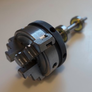 Figuring out what was wrong with that PCB would advance that project even if the laser project crashed and burned. So it wasn’t that big a risk to jump ahead, and I was VERY eager to get building. I ordered a cute little 3 jaw chuck so the motorized axis would be able to hold cylindrical stock of various sizes. The only down side to the chuck was that I’d have to machine a shaft with a very concentric 1mm thread. Not a big deal, but an additional hurdle for other folks wanting to build a rig like this.
I did write up that machining job, mostly so I’ll have something to refer to the next time I need to do single point threading.
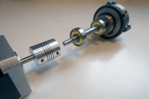 The rig is direct drive using a stepper motor, a zero backlash coupling, and two 608 skateboard bearings. As Lawrence worked on a way to extract the silhouette profile curves and export them as .svg files, I worked on the most basic version of the device. I used an Arduino Nano and a little stepper motor controller all wired up a on protoboard with a button to advance 1/16th of a turn.
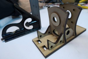 When TechShop reopened, I lasercut the rig to hold the motor, bearings, and chuck so I could glue it together. Lawrence had gotten his profile curve extraction code working, so we were finally ready to do a basic test of the idea.
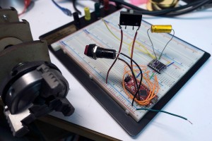 Instead of having a fully automated cut-out in these initial tests, the idea was to export each of the profiles as their own print job. We could print them out manually pressing the advance 1/16 button between each file.
Here you can see our very hairy initial setup. The Arduino Nano is in red and the stepper driver in purple. Look Ma, no heat sink!
The First Night
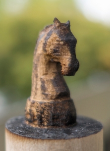
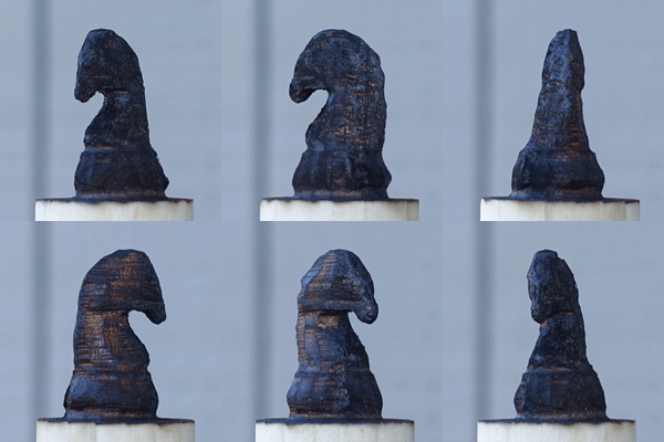 Our initial test model was a chess knight. We started by chucking in a 3″ length of 1″ poplar dowel into the motorized chuck. We figured we could keep printing the same profile until we cut all the way though and then hit the advance button and move on to the next profile. One cut, 2 cuts, 3, 4, 5, 6, 7,8,9,10,11, finally it cut though. That was a lot of cuts. The wood was pretty charred. We knew the subsequent cuts would be quicker because of all the material removed by that first huge cut, so we continued on. Lawrence loaded, configured, and printed each of the profile cuts, and I opened up the laser, pressed the advance button, closed it back up, and fired off the next cut. Like a pair of bureaucratic button-pushing relay racers, we finally made it to the finish line. The results? The knight was pretty charred and battle scarred. His ears burnt entirely away, but he was recognizably a knight! We were jubilant.
The Second Night
One of the reasons the laser was taking so many passes was that the thick material had a lot of material far from the focal plane, and that meant more charring and less cutting from the laser. We realized that although we couldn’t move the model vertically, we could have the focal point above the center of the model, and then by rotating 180 deg and cutting the mirror image of the profile we could effectively cut the same profile with the laser focus at two different levels.
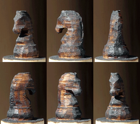 So I added a button to the rig that would rotate the model 180 deg. The first time we tried to cut the mirrored profile after 180 deg rotation, we discovered that the laser’s idea of the center of rotation was off from ours. We needed to measure and adjust for the offset. After compensating for that, offset the idea worked. We once again did the tag-team cutting process, this time with a somewhat more complicated sequence of rotations that we checked off on a list. By the end of the night, we’d managed to cut out a less charred and scared knight! We even had some ear nubs! We were getting better step by step.
Can you use acrylic rod?
We did try this system on acrylic. Acrylic cuts very cleanly with no charring, and we thought it might have great results, but the process really depends on chunks of material being able to fall away. However, when slowly cut, thick acrylic has the tendency to melt just enough to make the chunks stick and not fall away. We decided to focus on wood for now, with the idea of revisiting acrylic at a later date.
Process Improvements
What were the next big steps? We realized that with better path planning, we could cut thin layers off the side of the rod in multiple passes to minimize the thickness we needed to cut at any one time. This spiraling-in process would allow us to cut each outline only once. We also wanted to add some cut lines to the outside edge of the material so the cut chunks would drop away more easily. Lawrence worked on those things, while I worked on building some sort of laser sensor so we could automate the rotary axis motions. Sitting around with a checklists pushing buttons was not a viable way to be doing this with ever-more-complicated cut sequences.
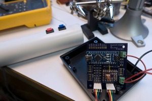 I built a better two-button remote from some PVC, so we could at least not have to open the laser between passes. I also finally got around to troubleshooting the PCBs I’d had made for the camera motion rig. It turns out the Arduino Nano package I’d downloaded from the internet was for V2 of the Nano, but I had V3. For some unknown reason, they had reversed the order of the analog pins, which is a fatal change if you’re using most of the analog pins for digital IO. Once I had that fixed in software, the board was only 1 oops wire away from being fully functional, so in an evening I was able to go from hairy protoboard to svelte PCB.
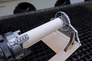 I also made a centering jig that made it easy to put the rods into the chuck nicely centered. That way I could quickly chuck new rods without quite as much tapping and fiddling to get them to spin without a wobble. The next big improvement was a way to automatically advance the rig though its rotations as the laser went through its sequence. It would be so nice to be able to just hit “print” and have this system cut out a 3D model.
Blind to the Laser
My first inclination was to use some sort of IR photo transistor to watch the laser pulses and get a sense for when the laser was on versus off, and from there we could keep track of where we were in the sequence and when to advance. We could also in theory eventually use a sequence of laser flashes to communicate rotation sequence information to the rig. That way a single print job could handle everything. There was just one BIG problem with this idea, but thus far I was blind to it.
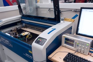 I built an ATTiny85-based pulse train detector and put it in the laser bed. No reaction. I tried some other random IR photodiodes/transistors I had around. Still no dice. I hooked up a scope and saw zero evidence of the detector seeing the laser at all! I thought maybe the pulses were just so short that the system couldn’t see them, but then I did some more research. It turned out that the IR emitted by a big CO2 laser is totally out of the range of cheap IR phototransistors. In fact, room temperature versions of such devices had only recently become available and they were $800 used on eBay! Not an option for us. It’s counter intuitive that something so powerful that you can be blinded by even diffuse refection of its light can be entirely undetectable by cheap electronics, but there it was. I’d taken the project up a bind alley.
Acorn Nut Job
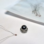 My backup plan was to use a thermistor armored in a small acorn nut. The reaction time would be quite slow, but it was simple. The acorn nut would protect the thermistor, and we could make the cutting sequence include having the laser blast the thermistor whenever the rotation rig was supposed to go to the next position. Hopefully, it wouldn’t get too hot over time.
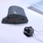 I used a dab of heat-sinking compound on the tip of the thermistor and a glob of epoxy putty to turn the delicate glass thermistor into an armored frankensensor. When I measured across the terminals to make sure I hadn’t shorted them out I noticed the thermistor value was drifting. I was seeing the temperature rise of the epoxy setting! So that was working.
This slow sensor did mean we were going to need a different way to load sequences into the rotation rig. There was no way a system like this was fast enough to communicate a sequence of angles. Luckily, I had another way of doing this. My motorized camera rig used Bluetooth LE to communicate wirelessly to an app on my phone. It’s only 9600 baud, but it works well and lets you have all a full-on user interface running on a device you already have in your pocket. Much better than my huge PVC-wired remote. Best of all, I had already written an app that scanned and connected to this kind of bluetooth device, so I was able to quickly hack that up into an app to control the rig. An iOS app isn’t really that open though, so I was kind of sad to be adding this particular step to our tool chain. I gave the app the ability to receive sequences via deep link.
The Biggest Problem
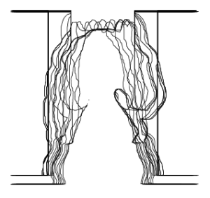 We had, however, discovered a huge problem with our plan, a problem that was going to take weeks to resolve. I had been told by someone at TechShop that if you turned off “Smart Vector Sorting” in the lasers print dialog, the laser would output the vectors from back to front. Perfect! We could output SVG, import into Illustrator, and print it out. Sadly, that turned out to not be true. In fact, the order in which the vectors are cut out is entirely out of your control. #%@$#! The vectors seem to be roughly y sorted and that’s that. God help you if you want to cut a zillion curves that are all in the same place. I exchanged emails with folks at Epilog with no real help. This is not exactly a big priority for folks using a laser in its normal 2D capacity. For a little while, we worked around this by having one super long cut vector, but that was never going to work for models with holes, etc.
We noticed a project called Ctrl-Cut on Git Hub that was a third party laser control program for the Epilog Legend 36EXT. Perhaps we could get it to work for the Fusion 120? I contacted Amir, and he was super helpful and generous with his time. I output various print files for him to look at, and he tried making a special cut of Ctrl-Cut for the Fusion 120 which would output the vectors in order. Progress was slow since I could only get on the laser one night a week. The printer files he was generating still had some issues and would crash the laser, which was pretty scary. Meanwhile, in the background, Lawrence was picking though the raw printer output and trying to get his path planning scripts to output the printers .prn files directly. Eventually, Lawrence was successful and he was able to generate .prn files, and we could even change the speed and power settings between cuts in the same file. Awesome! For this, I hereby award Lawrence an honorary knighthood, and a special shout out to Amir for his help and ctrl-cut examples.
Raster mode awesomeness
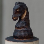 One of the shortcomings of the system of cutting out a bunch of profiles is that you can’t get details that never appear on the silhouette edge of the model. Laser cutters have a “raster” mode where they sweep back and forth quickly and etch an image into the surface. The power of the laser at any point is modulated by the color of an input image. Because this is used to etch a bass relief, I knew it could be used to carve in details which were missed by the profile-cutting passes.
There were details I wanted to be able to faithfully reproduce in the wood, like the eye of the horse and the curve in behind the jaw. I hand drew a few details and tried applying them to the side of one our burnt knights.
To our surprise, the raster pass not only etched in the details, it also blasted away the surface material charred by the slower vector cutting passes. We realized that we may well be able to have entirely non-charred output by simply leaving a thin layer of extra wood on the surface and removing it later with a raster pass.
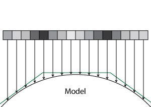
I had a feeling we could use these raster adjustments to cut out a model very close to the shape of the original model. I really wanted to see that in action, so I learned a bit of Scene Kit and wrote a quick system that could draw all the laser cutting passes as geometry, and then fire rays though them to find the distance from the closest hull to the model. This distance controls the darkness of that pixel in the raster image, which in turn controls the amount of material removed by the laser. This was going to be great!
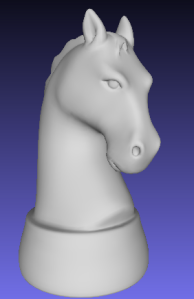
There was just one problem. On closer inspection of our knight model, I realized that it didn’t have much in the way of eye or nostril detail. They were just painted on in textures and not modeled into the surface at all! This fancy ray tracing system was going to be very useful with our not very detailed model. Not wanting to abandon the knight, I cast around for help. I don’t have much in the way of modeling chops, so I knew touching up our model was way beyond me. Having spent more that 8 years as an R&D developer at PDI Dreamworks, I had a few contacts who were up to the task. After asking around for help, Joshua West stepped up and entirely remodeled the knight for us! My Hero! So it was back to the races, armed with his slick new model. I used my rendering system to render out a Visual Hull To Model Offset Map or “Stripy Horse Picture.”
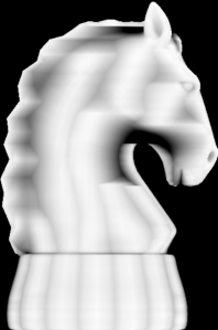 Now we were talking! You can see how the inner ear, eye, mouth, and nostril are all represented. You can see how the raster is compensating for the faceting of the round base and the deep inset under the jaw, etc. I’d had this image in my head for months, and finally I had it rendered out where other people could see it. Now to see what happens when we apply it to one of our scorched and faceted knights.
Meanwhile, Lawrence had started porting his path planning code to a web app that turned out to be both much faster and more convenient than the python scrip we had been using. We were about to try a number of firsts all in one night. Our first fully automated cutting of the model with the thermal-switch advancing the rotary rig. Our first use of the new speedier web app for path planning and our first (admittedly hand aligned) attempt at fine tuning the model with a automatically generated raster pass.
We had a few false starts: I had to add even more averaging of the thermal sensor to smooth out motor noise that was causing false triggers, and Lawrence had to add back in the “burn a line on the thermal sensor” path segments which had gotten left behind in the port. We managed to get the thing cut out and rastered up, and I’ll be damned if it didn’t look pretty darn good!
You can see the eye detail, nostril, the jaw line, even the inside of the ear came out! We were ecstatic. There it was, 3D model to wooden model in only a few minutes worth of laser time! The dark lines on the model are actually the places where the model wasn’t touched by the raster pass. Kind of the negative of the dark lines in my rendering. I think, with the addition of a small amount of protective material left on for the raster pass to remove, we should be able to have a mostly-not-burnt looking knight.
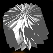
We were so excited that we cut out another one, and when that came out we decided to go for broke and cut out a long DNA-shaped helix model. It was our first attempt at a model other than the knight. It was looking pretty neat, but near the end the thermal sensor missed one of the rotation signals. The final pass cut the twisted ladder away, rung by rung, until there was nothing left. Oops.
If you’d like to see the code, and the PCB designs you can check them out on github.


Pingback: 3D Objects From a Laser Cutter | Hackaday
Try using a thermocouple instead of a thermistor. They have a much faster response time and can take the heat of the laser beam. You may have to amplify the output signal since it is in the millivolt range.
Not a bad idea, but it ups the price and electronic complexity a bit. It also might be more sensitive to the giant piles of electrical noise from the stepper motor, etc. A thermocouple would be a bit faster but unless it’s “useful amounts of data transmission fast” the speed isn’t a huge issue. I could make the thermistor quite a bit faster by using a smaller metal shield. :]
Hello,
I can’t find any contact info in the site so forgive me for using the comment section. I’m Algen, I work with engineering website EEWeb.com and would love to have your website featured as a site of the day on EEWeb. Is this of interest to you?
Hope to hear from you soon.
Sincerely,
Algen
Pingback: Waarom 3D-printen als je kan laseren? - Mancave
Pingback: Laser Cut-and-Weld Makes 3D Objects | Hackaday
Hi there, I’ve been looking for someone who can achieve something like this for a while, as I’ve been wanting to make a wooden Lego figure with varying degrees of success. If you think that this could achieve such a thing, please contact me at 208luma@gmail.com and we can talk details.