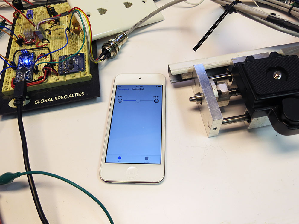
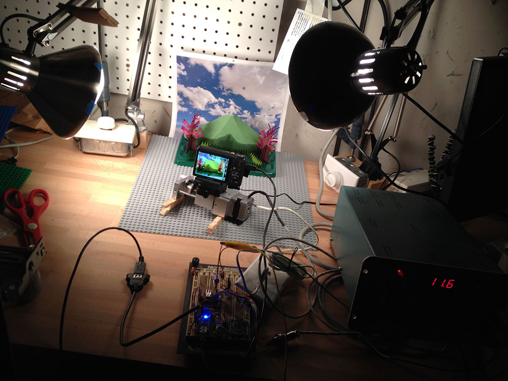
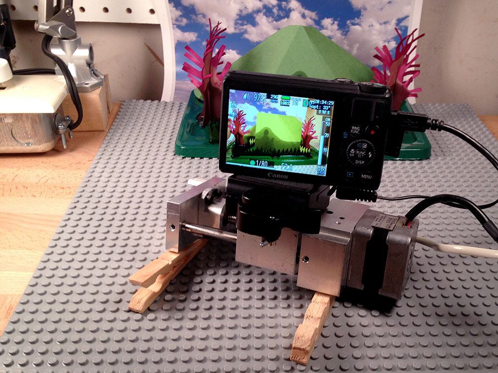
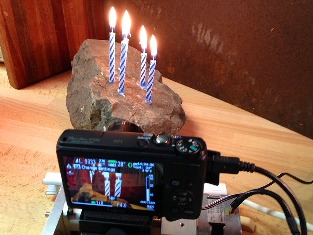
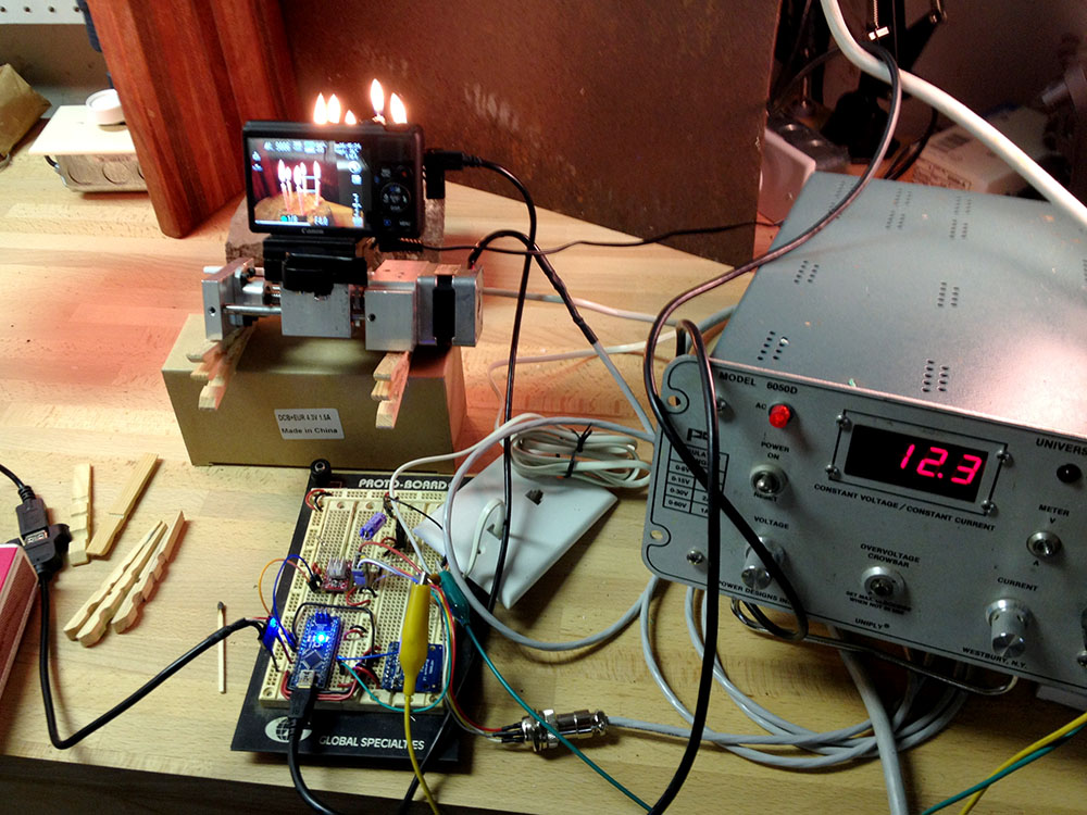
I’ve been making progress on the camera motion rig, but it is a not very portable mass of protoboards, wires, alligator clips, and bench-top power supplies. It works, but it took me 15 minutes just to move it from one table to another. At this point in a project, you have a few options. You can solder the components onto some perfboard and direct wire up all the connections. That’s nice and immediate and makes it fairly rugged, but what you end up with is an ugly one-off board. Another option is to make a printed circuit board. I’ve been etching them since the days of rub off letters/pads/traces, when I’d spend hours with an Exact-o knife and a rubbing stylus. Then for years, I used various toner transfer methods. These methods let you print your design out on a laser printer, and then transfer the toner onto a copper clad board. The toner acts as the resist and you etch away the rest of the copper. Finally, a process where making the second board was a lot simpler than making the first one. Still it was a pain because getting super clear transfers is a bit tricky, and aligning a second layer is a pain. You spend a lot of time touching things up. On the bright side, you can have the board the very same day. I’ve been doing this for years, but the price of getting PCB’s made has been dropping and dropping. So I finally decided to have the PCB’s for the camera control rig commercially made.
  I downloaded the free version of Eagle CAD. It lets you design boards with some limitations in terms of size and number of layers, but it seemed like it would work for me and, hey, it’s free. Jeremy Blum has a nice set of video tutorials about the basics of Eagle CAD. My project is a little strange for a first attempt at a board because it is made up of a number of individual daughter boards. There’s the Arduino Nano, the Bluetooth Break Out Board, and the stepper motor driver board. Instead of starting by plopping down standard library components, I had to dive right in the deep end and start defining my own custom components. Sparkfun has a bunch of good Eagle tutorials, including one that walked me though making my own part. I spent the entire first evening just making the two missing devices. That tutorial is really aimed at surface mount devices so I kind of had to wing the though hole part.
  Every device has a symbol which is what shows up in the schematic, and one or more packages which match the physical shape of the device. So for example a 555 timer chip has a single schematic symbol, but then can come in a tiny surface mount package, or a much bigger through hole version. I was so exited when I finally got to the stage of being able to plop down my three main components and wire them together. On the second night I wired up the rest of the schematic. That would normally be fast, but as you add components you have to always pick exactly which physical component you’re going to use. It’s not just 100uF Capacitor, it’s a 100uF Capacitor with radial 3.5mm though hole pads and 8mm spacing. Thankfully I was only using one resistor type, two types of capacitors, and two kinds of connectors. So it took a while, but not crazy amount of additional time. I think onece you have sort of built up a arsenal of devices you tend to use in projects that part will be much faster and less painful.

Final Schematic
By the end of that evening I had wired everything up. I noticed I still had some unused Arduino pins. So I added a tri color status led, and a voltage divider so I could monitor the 12 volt supply in case it was being driven from a battery. That way I could support a low battery warnings, etc. I also pushed the last few pins out to an aux port so I could add things like an external trigger button or jog knob later if needed. Then I was ready to take a stab at routing the board.
Footprint Problems
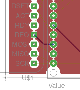
It was then that I saw various problems with my hand built parts. I’d manually put holes though the pads which was redundant and was also causing an exclusion zone around those pins. My ground plane was avoiding those pins like the plage. Heck even the Nano part lib I’d downloaded had to have the corner dill holes removed. Also my extensive naming of things had really cluttered up my silk screen layer, and Eagle’s Smash Part command which lets you move the name/value around independently wouldn’t let me move those silk screens around. *sigh*  The third night I spent reworking my custom devices, beefing up the various power lines, fiddling around with labels, adding holes for mounting screws, and being generally anal retentive. I spent a while trying to use Net Classes so the auto router would beef up the supply lines on it’s own, but for some reason it just was not having any effect. I used the RIPUP; command a lot during that period. It rips up all the routing on the board. In the end there were only a few short runs that needed to be really beefy so I just routed them by hand. Ok so the board was mostly ready to go. Now I had to get the thing built. You can get Eagle to export GERBER files which define the various layers, have separate files for the layers, holes, solder masks, etc. All the files need to have the right names and file extensions. It’s all very fiddly. Thankfully there are CAM job files you can download that will take various layers in Eagle and spit out a pile of properly named GERBER files. So it’s a mostly automated process. Then you zip those files into a single file and you’re ready to try sending them to some board manufacturers. Jeremy Blum’s third video goes over doing this, and he has a Job file you can use. His third video has a lot of tedious “putting together a bill of materials” section. That’s probably the only really bouring thing in his otherwise awesome videos. If you already know how to select parts (which you practially had to do to decide on parts for your layout) you can skip the middle third of that video. Lady Ada has a page comparing the various manufacturers.
  I decided to try OSH Park first. Just because I liked the sound of $5 a square inch for three boards and free shipping. For small boards that seemed ideal. It turned out all that fiddling around making GERBER files and CAM job messiness was totally unnecessary. OSH Park takes Eagle board files, and a few seconds later you’re looking at beautifully rendered views of the various layers of your board. Their boards have both top and bottom silk screens and are purple with gold plated pads. So swanky. They quoted me $29 for three boards. I was so swept away by the simplicity and the nice looking layers that I just fired it off. I was so excited. A few minutes later I realized I hadn’t done the one test I had really wanted to do. Printing out a scale version of the pads and making sure I had all the spacings correct on my home brew parts. It was late at night at this point but I just HAD to know. I wasn’t going to sleep well wondering if I’d have to wait 12 days to get 3 pieces of unusable purple and gold junk. Sadly my laptop isn’t connected to a printer so I tried exporting to .pdf and emailing that to myself so I could print in from our desktop machine. When I printed it out the sizes where all screwed up. Either everything was off, or the scale was getting fiddled. Googling around it sounded like others were having scale problems with pdf’s. So I saved the file as postscript. Sent that to myself and then I had to figure out how to send a .ps file to a postscript printer from Windows 7. You’d think that would be trivial, but you’d be wrong. I ended up having to install both ghostscript and the gsview postscript viewer before I could finally print it out. By then it was well past 1am, but I just HAD to know. This time it printed out properly. The pin headers had the right spacing the Nano matched, but horror or horrors the stepper motor driver’s two rows of pins where one step too close together!
Stop the presses!
Thankfully OSH Park batches your job up with a bunch of others so I was able to get them to cancel my board without a hickup. I’m sure I wasn’t making my best first impression with them. Oops. I got up early and reworked that part’s foot print for the second time. I hand re-routed the power lines again, and soon I was back looking at the awesome purple eye candy.  Would I hit the Buy Button this time? No. This time I was a bit more catihous. I noticed that on the actual CAM output of the board they were cutting the ground planes into strips. That probably helps cut down on eddy current noise or something, but there were a few places where I was depending on that plane to conduct the full motor current. I decided to go back and direct draw a few fat lines in those areas. Also there was a place where an important pad had copper removed around the corners to make it easier to solder. Soldering to a full copper plane is a pain since it skins so much heat. For this one important pad there were only two small tabs connecting it to the ground plane. I fattened that one up to .056mm hopefully striking a better balance between solderablity and current.
  I also realized that OSH Park includes a bottom silk screen that I hadn’t used at all because I didn’t want to pay for that. I quickly moved a few notations down to the bottom just so the board would look nicer. Bottom silk screens are nice because that’s often where you’re poking around with probes trying to trouble shoot things. Well at least for through hole projects. Now finally when I was scrutinizing those purple and gold lovelies rendered on the OSH Park site I decided to pull the pin. There are two capacitor pads that I wish were a bit bigger. I think they may be hard to solder, but I declare it good enough. I also experimented with converting the stepper board from normal round pads to the old style wide pads. This way I can compare solderability. That day we were going to a friends birthday party and Cheryl and I both wore purple and gold to celebrate my first board send off. Now I have to wait 12 days for the boards to show up. What the heck will I do? I guess I can try some more time lapses and maybe start work on the enclosure. Apparently I’m also doing a blog post. So far I’ve been very happy with OSH Park. Their upload and verification stuff is slick and simple. Since I’m already using Eagle it really could not be easier. They also let me cancel my one rouge order. I tried uploading my project to Seeed Studio and their site seemed to be telling me that it would be $9 for 10 boards which has to be wrong but there was no detailed feedback about the order and I couldn’t tell what was wrong. For prototyping I think OSH Park is worth it. If I get to a point where I want to make more than 3 boards I’ll have to try someone else. Now I just have to hope I haven’t screwed anything else up. Are the 12 days over yet!?


 So I ordered one of the boards, and I was off to the races. Adafruit’s page about wiring up the board is very clear, and I hooked up an Arduino UNO just to try it out. I was able to get their UART echo communication going right away. Simple, Pimple.