Cutting 3D Shapes on a Laser Cutter

twoKnightsWhen my local TechShop got a 120-Watt Epilog Fusion laser cutter, I knew it was time to try out something new. Being able to cut though fairly thick material made me wonder if it was possible to cut out 3D objects with the laser. Most laser cutters produce 2D output. They either cut and etch sheets of material in X & Y, or they cut and etch cylindrical objects (drinking glasses, etc) by turning them with a rotary axis which replaces the Y motion. In the past, I’ve sometimes used an indexing jig to turn the object and make XY cutting passes at various angles. What if I automated this rotation? Could I produce a 3D object by rotating the object and cutting out various 2D silhouette profiles? The process is limited buy the max cutting thickness of the laser. You can’t hack an object out of a spinning 2″ rod of material if the max you can cut though is 1/4″.

The new 120-Watt laser seemed like it might be powerful enough make this idea practical.  I’d never seen anyone do this sort of work with a standard laser cutter. In industry, it’s common to add additional axes to cut at angles, but this XY plus rotational axis (A) was hard to google for. I liked the general shape of the project. At first, I could make a simple rotational jig and manually run a profile cuts though the laser just to see if there was any hope for the idea. If it seemed like it was possible, I could build a motorized A axis and use an optical sensor to sync it to the laser’s motion. From there, all sorts of interesting things could be done in the software to improve the output.

Hey we were featured on Hack-A-Day!

I find a partner in crime

I was pretty excited about the project, and I knew it was going to involve a fair amount of software and hardware. I wrote a super long email to my friend Lawrence pitching the idea. A few hours later he sent me an animated gif of a test model’s rotating silhouette. Clearly, he was in and already on the case! Woot! Lawrence and I have done a number of projects together, including the solar plotter project. He’s great to work with. I knew that with him on board, this project might really have some legs.
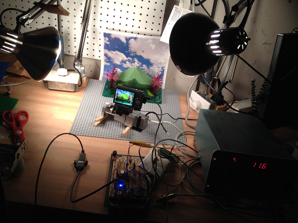
Right at this point, my TechShop announced that they were moving to a new location. The laser was going to be unavailable for a few weeks, so I decided to skip ahead and build a motorized A axis. This might’ve seemed overzealous. Why not do some tests with a manual jig first? Well, I was excited about the project and wanted to start building. As an added bonus, building the motorized version would get me to finally troubleshoot the PCB’s I’d designed for my motorized camera rig.

chuckAndShaft
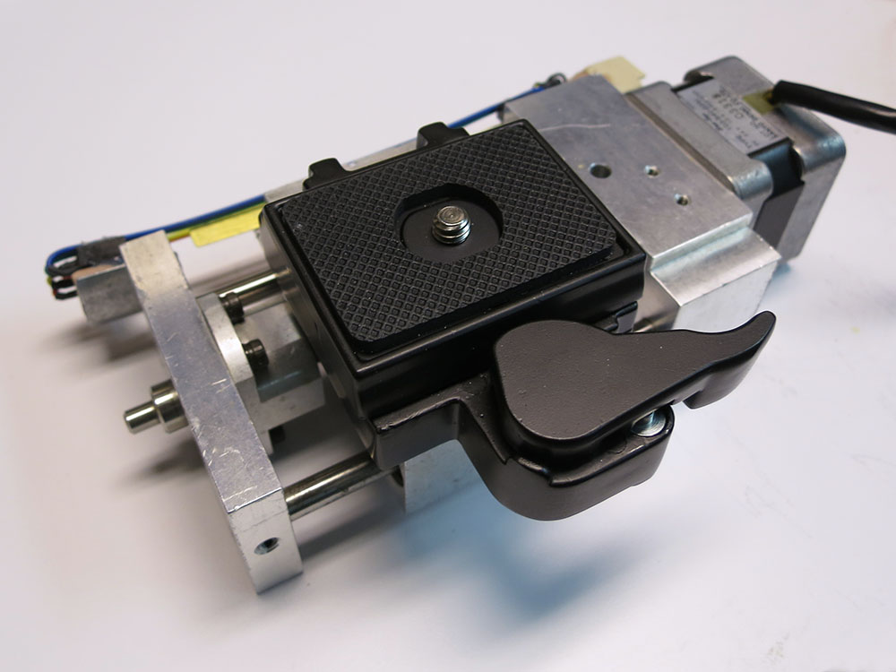
Figuring out what was wrong with that PCB would advance that project even if the laser project crashed and burned. So it wasn’t that big a risk to jump ahead, and I was VERY eager to get building. I ordered a cute little 3 jaw chuck so the motorized axis would be able to hold cylindrical stock of various sizes. The only down side to the chuck was that I’d have to machine a shaft with a very concentric 1mm thread. Not a big deal, but an additional hurdle for other folks wanting to build a rig like this.

I did write up that machining job, mostly so I’ll have something to refer to the next time I need to do single point threading.

DSC01277
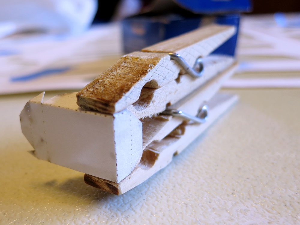
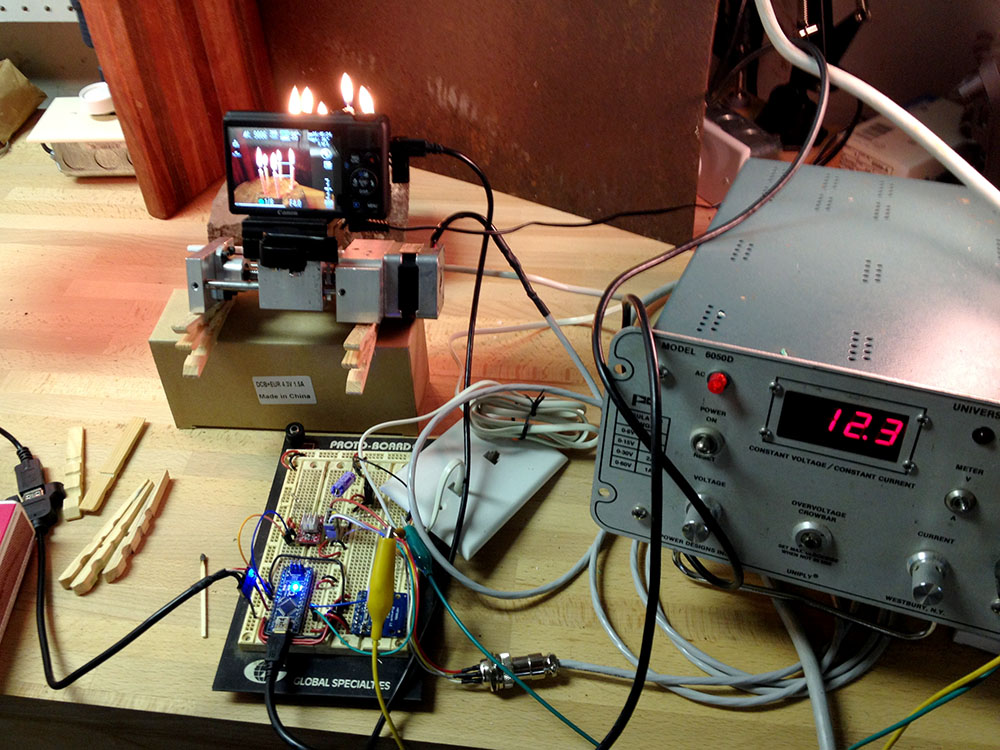
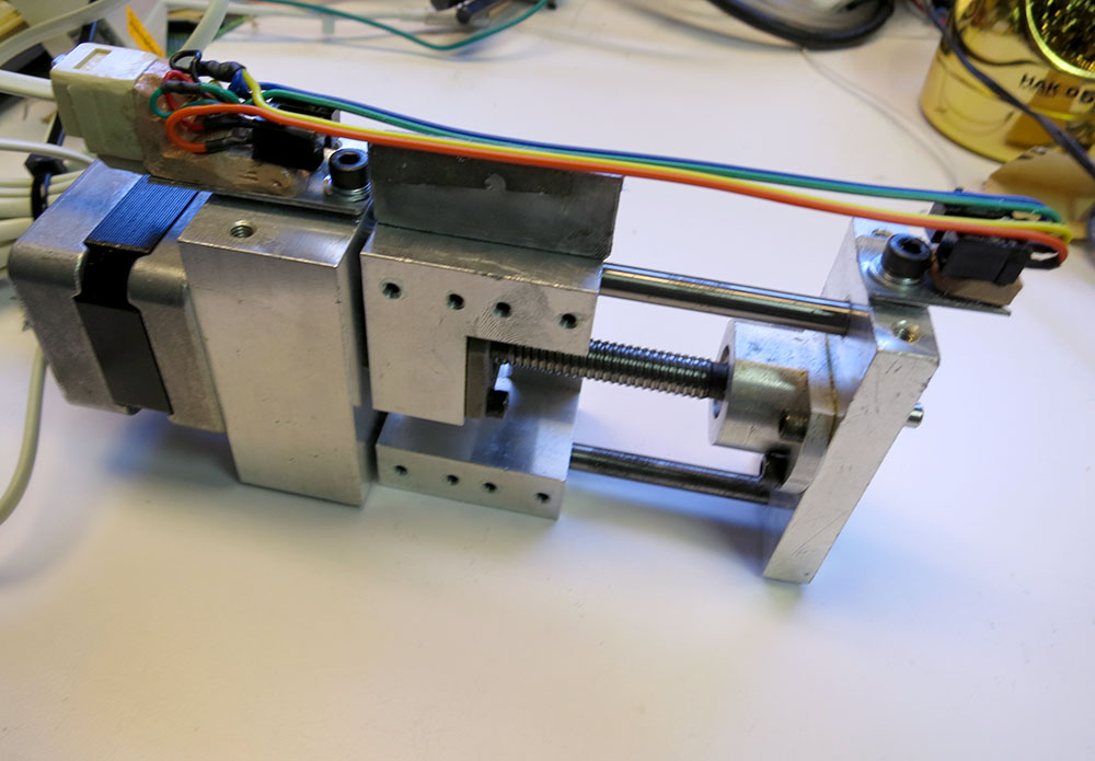
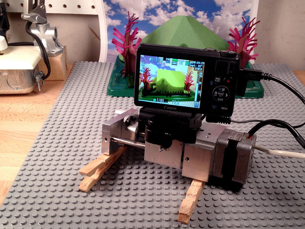
The rig is direct drive using a stepper motor, a zero backlash coupling, and two 608 skateboard bearings.  As Lawrence worked on a way to extract the silhouette profile curves and export them as .svg files, I worked on the most basic version of the device. I used an Arduino Nano and a little stepper motor controller all wired up a on protoboard with a button to advance 1/16th of a turn.
Chuck Stand Looks Like Monsters
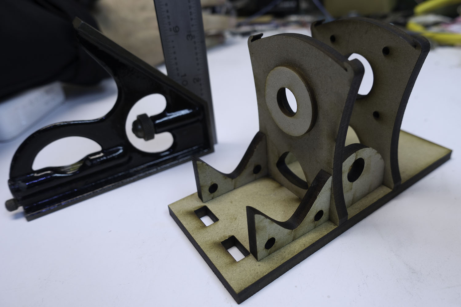
When TechShop reopened, I lasercut the rig to hold the motor, bearings, and chuck so I could glue it together. Lawrence had gotten his profile curve extraction code working, so we were finally ready to do a basic test of the idea.

twoButtonProtoboardInstead of having a fully automated cut-out in these initial tests, the idea was to export each of the profiles as their own print job. We could print them out manually pressing the advance 1/16 button between each file.

Here you can see our very hairy initial setup. The Arduino Nano is in red and the stepper driver in purple. Look Ma, no heat sink!

The First Night

FirstKnightSpinSmall
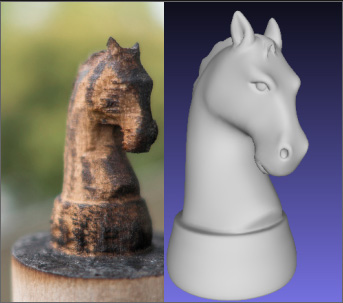
Our initial test model was a chess knight. We started by chucking in a 3″ length of 1″ poplar dowel into the motorized chuck. We figured we could keep printing the same profile until we cut all the way though and then hit the advance button and move on to the next profile. One cut, 2 cuts, 3, 4, 5, 6, 7,8,9,10,11, finally it cut though. That was a lot of cuts. The wood was pretty charred. We knew the subsequent cuts would be quicker because of all the material removed by that first huge cut, so we continued on. Lawrence loaded, configured, and printed each of the profile cuts, and I opened up the laser, pressed the advance button, closed it back up, and fired off the next cut. Like a pair of bureaucratic button-pushing relay racers, we finally made it to the finish line. The results? The knight was pretty charred and battle scarred. His ears burnt entirely away, but he was recognizably a knight! We were jubilant.

The Second Night

Knight Focal Plane

One of the reasons the laser was taking so many passes was that the thick material had a lot of material far from the focal plane, and that meant more charring and less cutting from the laser.  We realized that although we couldn’t move the model vertically, we could have the focal point above the center of the model, and then by rotating 180 deg and cutting the mirror image of the profile we could effectively cut the same profile with the laser focus at two different levels.

knightSpinSmallSo I added a button to the rig that would rotate the model 180 deg. The first time we tried to cut the mirrored profile after 180 deg rotation, we discovered that the laser’s idea of the center of rotation was off from ours.  We needed to measure and adjust for the offset. After compensating for that, offset the idea worked. We once again did the tag-team cutting process, this time with a somewhat more complicated sequence of rotations that we checked off on a list. By the end of the night, we’d managed to cut out a less charred and scared knight! We even had some ear nubs! We were getting better step by step.

Can you use acrylic rod?

We did try this system on acrylic. Acrylic cuts very cleanly with no charring, and we thought it might have great results, but the process really depends on chunks of material being able to fall away. However, when slowly cut, thick acrylic has the tendency to melt just enough to make the chunks stick and not fall away. We decided to focus on wood for now, with the idea of revisiting acrylic at a later date.

Process Improvements

What were the next big steps? We realized that with better path planning, we could cut thin layers off the side of the rod in multiple passes to minimize the thickness we needed to cut at any one time. This spiraling-in process would allow us to cut each outline only once. We also wanted to add some cut lines to the outside edge of the material so the cut chunks would drop away more easily. Lawrence worked on those things, while I worked on building some sort of laser sensor so we could automate the rotary axis motions. Sitting around with a checklists pushing buttons was not a viable way to be doing this with ever-more-complicated cut sequences.

pcbWithRemote
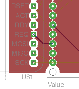
I built a better two-button remote from some PVC, so we could at least not have to open the laser between passes. I also finally got around to troubleshooting the PCBs I’d had made for the camera motion rig. It turns out the Arduino Nano package I’d downloaded from the internet was for V2 of the Nano, but I had V3. For some unknown reason, they had reversed the order of the analog pins, which is a fatal change if you’re using most of the analog pins for digital IO.  Once I had that fixed in software, the board was only 1 oops wire away from being fully functional, so in an evening I was able to go from hairy protoboard to svelte PCB.

centeringJigI also made a centering jig that made it easy to put the rods into the chuck nicely centered. That way I could quickly chuck new rods without quite as much tapping and fiddling to get them to spin without a wobble. The next big improvement was a way to automatically advance the rig though its rotations as the laser went through its sequence. It would be so nice to be able to just hit “print” and have this system cut out a 3D model.

Blind to the Laser

My first inclination was to use some sort of IR photo transistor to watch the laser pulses and get a sense for when the laser was on versus off, and from there we could keep track of where we were in the sequence and when to advance. We could also in theory eventually use a sequence of laser flashes to communicate rotation sequence information to the rig. That way a single print job could handle everything. There was just one BIG problem with this idea, but thus far I was blind to it.

laserAndScope I built an ATTiny85-based pulse train detector and put it in the laser bed. No reaction. I tried some other random IR photodiodes/transistors I had around.  Still no dice. I hooked up a scope and saw zero evidence of the detector seeing the laser at all! I thought maybe the pulses were just so short that the system couldn’t see them, but then I did some more research. It turned out that the IR emitted by a big CO2 laser is totally out of the range of cheap IR phototransistors. In fact, room temperature versions of such devices had only recently become available and they were $800 used on eBay! Not an option for us. It’s counter intuitive that something so powerful that you can be blinded by even diffuse refection of its light can be entirely undetectable by cheap electronics, but there it was. I’d taken the project up a bind alley.

Acorn Nut Job

acornNutAndThermistor
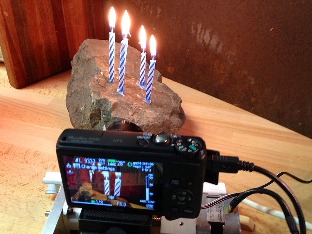
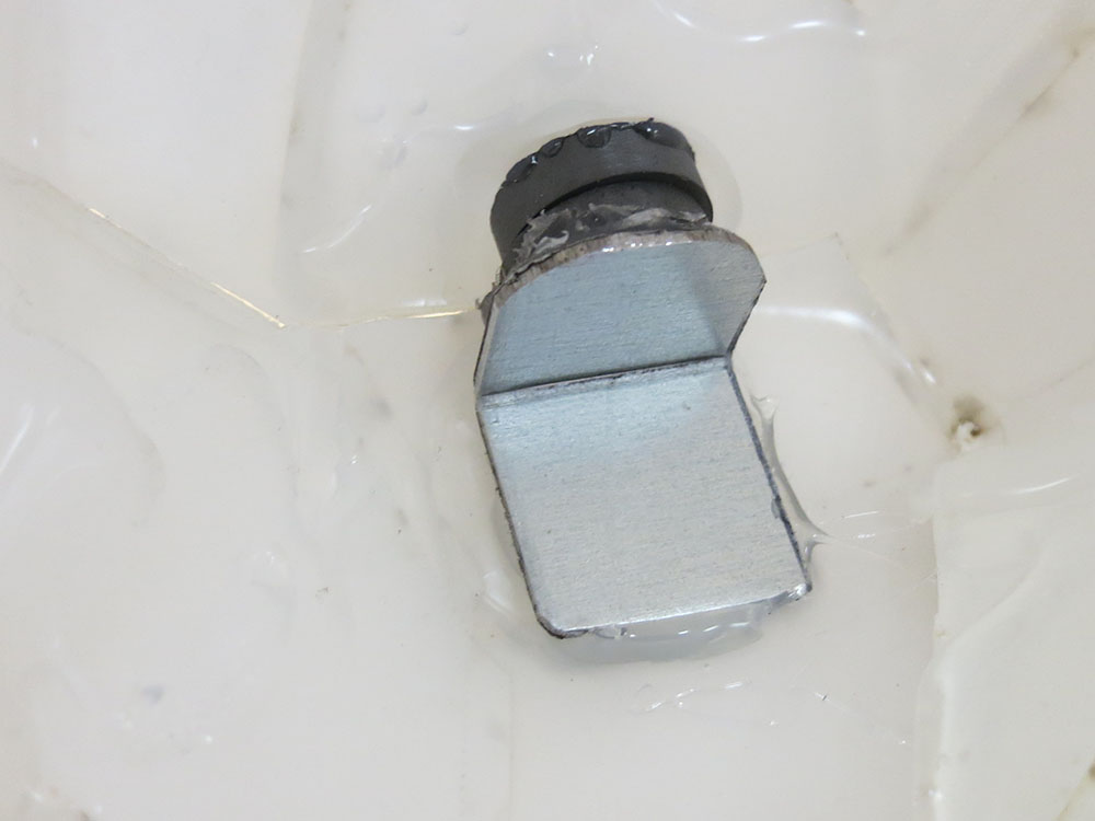
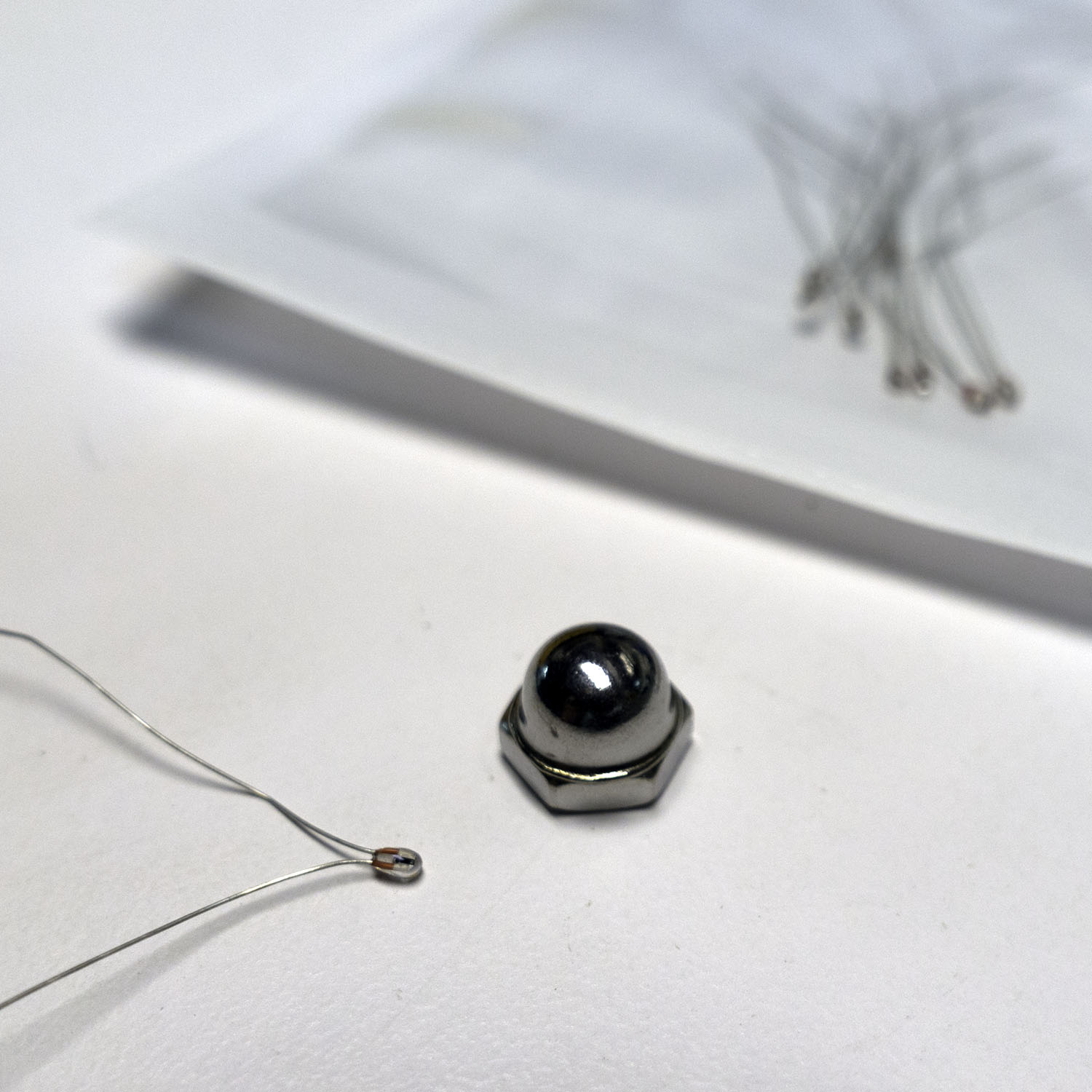
My backup plan was to use a thermistor armored in a small acorn nut.  The reaction time would be quite slow, but it was simple. The acorn nut would protect the thermistor, and we could make the cutting sequence include having the laser blast the thermistor whenever the rotation rig was supposed to go to the next position. Hopefully, it wouldn’t get too hot over time.


acornNutAndPuttyI used a dab of heat-sinking compound on the tip of the thermistor and a glob of epoxy putty to turn the delicate glass thermistor into an armored frankensensor.  When I measured across the terminals to make sure I hadn’t shorted them out I noticed the thermistor value was drifting.   I was seeing the temperature rise of the epoxy setting!  So that was working.

This slow sensor did mean we were going to need a different way to load sequences into the rotation rig. There was no way a system like this was fast enough to communicate a sequence of angles. Luckily, I had another way of doing this. My motorized camera rig used Bluetooth LE to communicate wirelessly to an app on my phone. It’s only 9600 baud, but it works well and lets you have all a full-on user interface running on a device you already have in your pocket. Much better than my huge PVC-wired remote. Best of all, I had already written an app that scanned and connected to this kind of bluetooth device, so I was able to quickly hack that up into an app to control the rig. An iOS app isn’t really that open though, so I was kind of sad to be adding this particular step to our tool chain. I gave the app the ability to receive sequences via deep link.

The Biggest Problem

knightProfilesWe had, however, discovered a huge problem with our plan, a problem that was going to take weeks to resolve. I had been told by someone at TechShop that if you turned off “Smart Vector Sorting” in the lasers print dialog, the laser would output the vectors from back to front. Perfect! We could output SVG, import into Illustrator, and print it out. Sadly, that turned out to not be true. In fact, the order in which the vectors are cut out is entirely out of your control.   #%@$#! The vectors seem to be roughly y sorted and that’s that. God help you if you want to cut a zillion curves that are all in the same place. I exchanged emails with folks at Epilog with no real help. This is not exactly a big priority for folks using  a laser in its normal 2D capacity. For a little while, we worked around this by having one super long cut vector, but that was never going to work for models with holes, etc.

We noticed a project called Ctrl-Cut on Git Hub that was a third party laser control program for the Epilog Legend 36EXT.  Perhaps we could get it to work for the Fusion 120? I contacted Amir, and he was super helpful and generous with his time. I output various print files for him to look at, and he tried making a special cut of Ctrl-Cut for the Fusion 120 which would output the vectors in order. Progress was slow since I could only get on the laser one night a week. The printer files he was generating still had some issues and would crash the laser, which was pretty scary. Meanwhile, in the background, Lawrence was picking though the raw printer output and trying to get his path planning scripts to output the printers .prn files directly. Eventually, Lawrence was successful and he was able to generate .prn files, and we could  even change the speed and power settings between cuts in the same file. Awesome! For this, I hereby award Lawrence an honorary knighthood, and a special shout out to Amir for his help and ctrl-cut examples.

Raster mode awesomeness

knightWithTestRasterOne of the shortcomings of the system of cutting out a bunch of profiles is that you can’t get details that never appear on the silhouette edge of the model. Laser cutters have a “raster” mode where they sweep back and forth quickly and etch an image into the surface. The power of the laser at any point is modulated by the color of an input image. Because this is used to etch a bass relief, I knew it could be used to carve in details which were missed by the profile-cutting passes.

There were details I wanted to be able to faithfully reproduce in the wood, like the eye of the horse and the curve in behind the jaw. I hand drew a few details and tried applying them to the side of one our burnt knights.

To our surprise, the raster pass not only etched in the details, it also blasted away the surface material charred by the slower vector cutting passes. We realized that we may well be able to have entirely non-charred output by simply leaving a thin layer of extra wood on the surface and removing it later with a raster pass.


KnightHullRenderingrasterExample

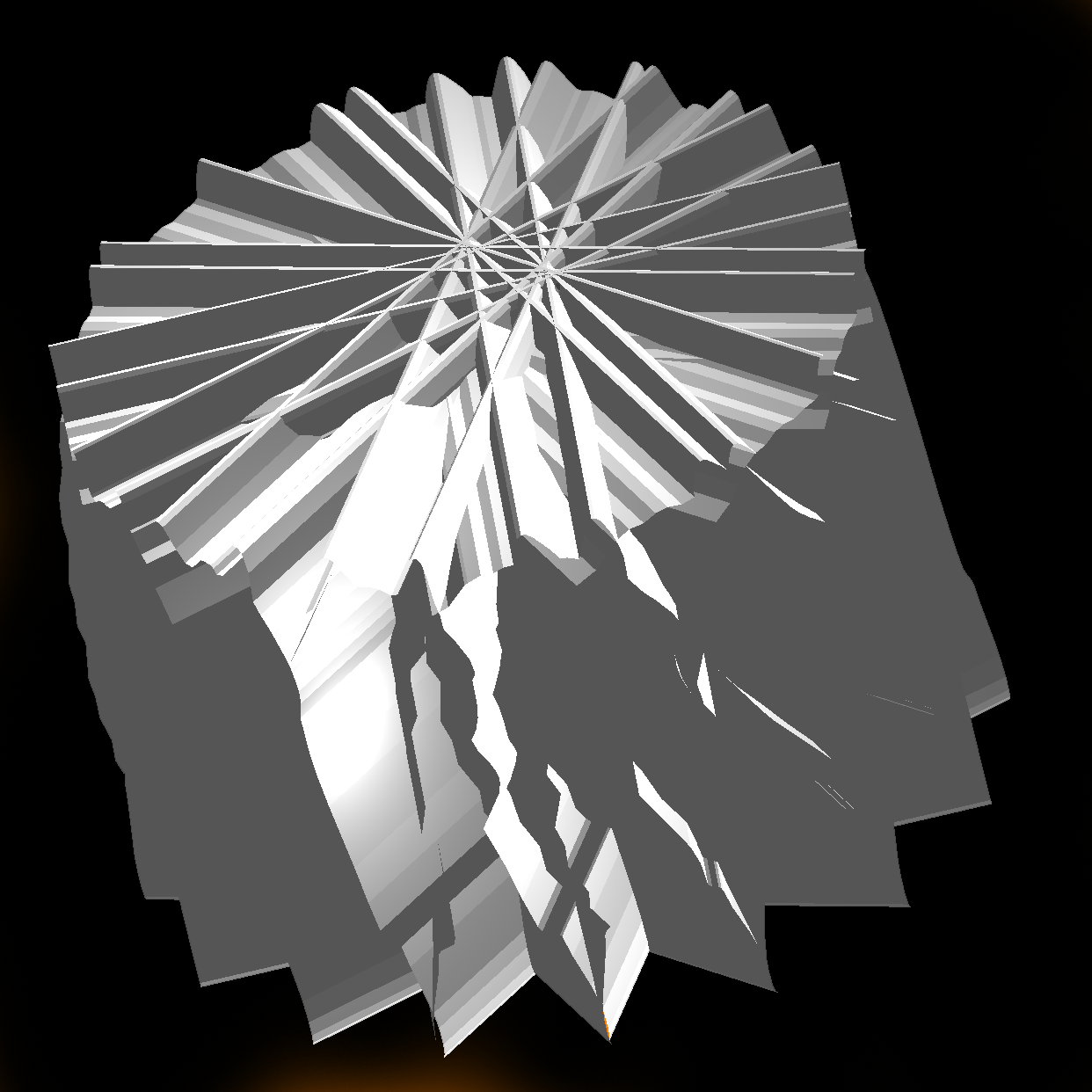
I had a feeling we could use these raster adjustments to cut out a model very close to the shape of the original model. I really wanted to see that in action, so I learned a bit of Scene Kit and wrote a quick system that could draw all the laser cutting passes as geometry, and then fire rays though them to find the distance from the closest hull to the model. This distance controls the darkness of that pixel in the raster image, which in turn controls the amount of material removed by the laser. This was going to be great!

There was just one problem. On closer inspection of our knight model, I realized that it didn’t have much in the way of eye or nostril detail. They were just painted on in textures and not modeled into the surface at all! This fancy ray tracing system was going to be very useful with our not very detailed model. Not wanting to abandon the knight, I cast around for help. I don’t have much in the way of modeling chops, so I knew touching up our model was way beyond me. Having spent more that 8 years as an R&D developer at PDI Dreamworks, I had a few contacts who were up to the task. After asking around for help, Joshua West stepped up and entirely remodeled the knight for us! My Hero! So it was back to the races, armed with his slick new model. I used my rendering system to render out a Visual Hull To Model Offset Map or “Stripy Horse Picture.”

horseRightPass1Now we were talking! You can see how the inner ear, eye, mouth, and nostril are all represented. You can see how the raster is compensating for the faceting of the round base and the deep inset under the jaw, etc. I’d had this image in my head for months, and finally I had it rendered out where other people could see it. Now to see what happens when we apply it to one of our scorched and faceted knights.

Meanwhile, Lawrence had started porting his path planning code to a web app that turned out to be both much faster and more convenient than the python scrip we had been using. We were about to try a number of firsts all in one night. Our first fully automated cutting of the model with the thermal-switch advancing the rotary rig. Our first use of the new speedier web app for path planning and our first (admittedly hand aligned) attempt at fine tuning the model with a automatically generated raster pass.

We had a few false starts: I had to add even more averaging of the thermal sensor to smooth out motor noise that was causing false triggers, and Lawrence had to add back in the “burn a line on the thermal sensor” path segments which had gotten left behind in the port. We managed to get the thing cut out and rastered up, and I’ll be damned if it didn’t look pretty darn good!

firstRasterPassKnight improvedKnightModel

You can see the eye detail, nostril, the jaw line, even the inside of the ear came out! We were ecstatic. There it was, 3D model to wooden model in only a few minutes worth of laser time! The dark lines on the model are actually the places where the model wasn’t touched by the raster pass. Kind of the negative of the dark lines in my rendering. I think, with the addition of a small amount of protective material left on for the raster pass to remove, we should be able to have a mostly-not-burnt looking knight.

We were so excited that we cut out another one, and when that came out we decided to go for broke and cut out a long DNA-shaped helix model. It was our first attempt at a model other than the knight. It was looking pretty neat, but near the end the thermal sensor missed one of the rotation signals. The final pass cut the twisted ladder away, rung by rung, until there was nothing left.  Oops.

If you’d like to see the code, and the PCB designs you can check them out on github.


Making a Bulbasaur Halloween Costume

My Little BulbasaurThis year Simon requested a Pokemon costume, specifically a Bulbasaur. I was glad his costume was going to be made of cloth, since his brother’s costume required no tailoring. I really look forward to Halloween as a time to release my inner seamstress.

I went to the fabric store with a picture of a Bulbasaur, and I got some material to build the costume. I chose a lightweight flannel that seemed to be reversible. That way I wouldn’t get stuck cutting something out the wrong way round. It was the perfect aqua-green color, and Simon could have fuzzy comfort.
Pants With MarkingsI chose fairly accurate colors for the body and spots, but I went for a more organic-looking material for the bulb. Something a little less GREEN. I also got some dark brown corduroy because I was hoping to make the bulb a functional backpack, which required a dark liner.

The costume was going to consist of four main elements: a shirt and pants with the proper color and markings, a hat that would be the Bulbasaur’s head, and a bulb on the back. I also got some armature wire and two small LED flashlights to build some lighted Attack Vines, but I marked that as a stretch goal. I like to incorporate lights into the kids costumes to help with Halloween safety, but I knew that the Attack Vines would stick out awkwardly.

I try to build Simon’s costumes as much like normal clothing as possible. He has to wear that stuff all day, and there have been a few costumes that he’s worn throughout the year. I think kids have to be a bit older to be willing to put up with a bulky uncomfortable costume.

This year I spent most of my time on his brother’s very complex Halo Master Chef costume, so I had to be able to make Simon’s costume fairly quickly. I spent two full days building his costume. On the first day, I built the shirt and pants. I just snagged one of his current shirts and a pair of pants to use as basic patterns. I used felt to add the Bulbasaur markings because that way I didn’t have to deal with hemming the edges.

Bulbasaur Toes
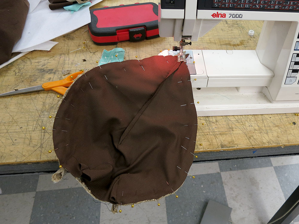
When I was making the toes for the pants, I realized I hadn’t brought any polyester fiber fill. I wasn’t going to waste an hour going to the fabric store to get some, so I just used my scissors to cut up some shreddies of material to fill the toes. It wasn’t as even as fiber fill, but the toes are small enough that it didn’t really matter.

When I got home, I had Simon try on the pants and shirt. To my horror, the pants were somewhat tight. I ended up adding a small panel at the side to make them a bit bigger. He loved the feel of the fuzzy flannel and really snuggled into the new outfit.

Head Pattern PieceshatPartsCuthatPartsComingTogether

On the second day, I had to build the hat and bulb. I had gotten a black baseball cap and some kid’s backpacks from the Goodwill. I always use an actual hat as the base for these kinds of head-hats because they already have a nice adjustment mechanism built in. I spent a few hours fine tuning the pattern for the head. I went through several yards of butcher paper and a bunch of tape testing various shapes. Finally, I got something that wasn’t too complicated but seemed to capture the shape of a Bulbasaur head. I was pleased with the results.
Ear Insert Close upActual Bulbasaurs don’t have a different inner ear color, but I added a cream triangle inside the ear to make the ears stand out and be a bit cuter. I used a very tight zig zag stitch to sort of embroider a wide line around the ear inserts, which was necessary because I didn’t have felt for that and I needed something to hem the cut edges of the cloth. I also thought it looked more cartoon-like than folding under the edges.

Upper Bulbasaur FaceI used the same system to put the dark green lines around the eyes. That was a bit hair-raising because at those slow feeds it’s easy to have the boarder bog down and drift away from the edge. I only had one shot. The second eye border came out better than the first.

I also used that same stitch to do the nostrils. Bulbasaurs have dark lines for eyebrows as well, but I decided there was much too high a chance of screwing up his expression free-handing on some eyebrows with no good way to undo them. I did not want to end up with an angry-looking Bulbasaur.

Bulbasaur Hat All DoneI put the pieces together and sewed it onto the hat. Then I stuffed and shaped it with fiber fill. I was really pleased with the way the hat came out. One of the TechShop employees even recognized it as a Bulbasaur, so I knew I was in the zone. Much better than “that frog thing.”

It was getting late, and I still needed to build the bulb. I made a paper “petal” and figured out what sort of tucks would give it the shape I wanted. I decided a 5-sided design would look nice and wouldn’t drive me completely crazy sewing up. I also thought 4 sides could form a bottom and 1 side to be sort of act as the top flap for the “functional backpack” goal.

Bulb Pieces Cut OutI cut out all 10 pieces and sewed them together. Weirdly the petals made wonderful looking ears. If I’d been working on some other costume that needed big donkey ears, I’d have been all set! Then I stitched the 5 petals together in an overlapping 5-sided ring, with the dark brown liner parts visible at each seam to add detail. Then I started looking at attaching this to one of the backpacks I’d purchased. I decided that I really didn’t want to do that. It was just too ugly to have those straps over his shoulders. So I instead sewed on a pentagonal base using my dark liner material.

Bulb Petals Lined UpBulb Pentagon Bottom

I figured I could add a zipper and use that to attach and remove the bulb from the shirt. Much nicer looking than straps, but he wouldn’t be able to cary much of a load in his bulb. I’d have to add the zipper later because it was late and all the sewing stores were closed. I ended up adding the zipper on the night before Halloween. I also put a beach ball inside the bulb to keep it fluffed up with minimum extra weight. I oriented the ball so the green part was the only part visible through the opening in the petals. It actually looked pretty good.

I made a mistake deciding to use a dab of hot glue at the end of the cut zipper to act as a stop to prevent the slider from coming off. This seemed like a better idea than just a big glob of stitches or something, but it was a fail. For one thing, the slider sometimes stuck against the glob, and at some point during his day at school, the bulb zipper slide fell off and got lost. Oops. I’ll have to go get another donor zipper, and Simon had to go without his bulb for actual trick or treating. Oh well. Slight fail, but I doubt he would have kept that thing on all night anyway.

Simon Bulbasaur On All FoursDuring his day at school, Simon ripped the crotch out of his pants, but I was able to sew them back together for trick or treating. A seven year old can really do a number on slightly tight pants. I guess I should have used some sort of stronger double seam for the crotch, but I don’t really know what kind is best, and I hadn’t had problems there in previous years. That lightweight flannel just wasn’t super strong.

noFaceBulbasaurstandingBulbasaurbulbasaurFromAbove

Simon really liked the costume. Fuzzy, Comfortable, and Cute. So apart from the zipper and crotch failures, this one was a success. Here is a video of Simon taking the costume for a spin.  I’m really proud that the face was recognizable as a Bulbasaur. The real question is, “Can a Bulbasaur take on a Halo Master Chef?”

“Bulbasaur, I choose YOU!”

bulbasaurVSHaloMasterChef


How to Build a Halo Master Chef Costume

No, that’s not a typo. This year I built my son a Halo Master Chef costume for Halloween. I love making Halloween costumes. They’re usually a wonderful excuse to do some sewing and pattern design. When my son asked to be “A Halo Spartan,” I knew I was in for a different kind of build. People who build Halo armor (There are more than you think!) often use a program called Pepakura to decompose 3-D models into paper cutouts. There’s a free viewer, and the full program is only $40. A few years ago, I built my son a Boba Fett helmet using Pepakura, and I’d already developed a system for outputting the designs and cutting them out of card stock using a laser cutter. There was still a lot of tedious gluing, but I could cut all the pieces out and perforate the fold lines, which makes it quite a bit quicker to assemble. I started building this set of armor mostly because the author had done a good job of providing the files and a spreadsheet to help you scale the costume parts.

Pioneer Ready for Night PatrolOne of the big issues with Pepakura builds is that you really want the scale to be correct. After gluing 200 pieces together is not the best time to figure out that your scale is off. I think if I were doing a Pepakura deconstruction, I’d provide two versions of the model. A super simple rough draft with only about 10 pieces that would have the basic shape and let you adjust the size, and then a fully detailed version for the complete build. I didn’t really have time to do that. Lots of folks spend a year building their armor, and I was only going to have a couple of weeks. So I downloaded the files, fiddled with the scales, laid out the parts for 24″x14″ card stock that could fit in the laser, and exported the vectors into Illustrator. The vectors already have styles to show mountain VS valley folds, but you have to adjust the spacing to work better on the laser. You don’t want the card stock to get too weak at the fold lines, so no long dashes. I used .4pt dots and 2.5pt spaces for valley folds and 1/2.83/.25/2.83 pt for mountain folds. You can use Select -> Same -> Appearance to select all the mountain/valley/cut lines and adjust them all at once.

Card stock in the laserWhen I laser cut the parts, I used 2′ x 2′ card stock purchased from Michael’s for $.75 a sheet. I cut each big sheet in half to make two. Because I’m not printing on the paper, I can’t include any of the edge alignment numbers. I had to keep all the parts organized in some way, so I used blue masking tape to hold the parts in their original cut positions, and just kept all the pages in a folder made from one of the card stock sheets. Then I had to use Pepakura to look up where each piece was in the cut sheets. It was a bit like doing a puzzle.  The torso has 200 parts on 6 sheets, and it was important that none of them went wandering off. Blue masking tape is very forgiving and can be pulled off without damaging the card stock. Don’t use normal masking tape, or you’ll be tearing your parts and then your hair out along with some gnashing of teeth.

Glueing SetupI used Elmer’s white glue for the gluing. It’s great for this task because it has a long enough working time to let you get things into position and holds well. The one down side is you sometimes have to hold things in position for 30 seconds or so in order to have it start to hold. I modified a few clothes pins by sawing off the tips, making them into more nimble paper-pinching helpers.


Modified Cloaths PinsThe clothes pins were super useful for holding paper edges together long enough for the glue to set. Because I was using pre-perforated folds, I mostly didn’t have to crease the fold lines, and the few that I did crease I could do freehand with a bone folder following the connect-the-dots style along the fold lines. I only did this on a handful of folds. All the others could just be done freehand thanks to the perforations.


bicep Back LitBicep On White CounterArm On White Counter
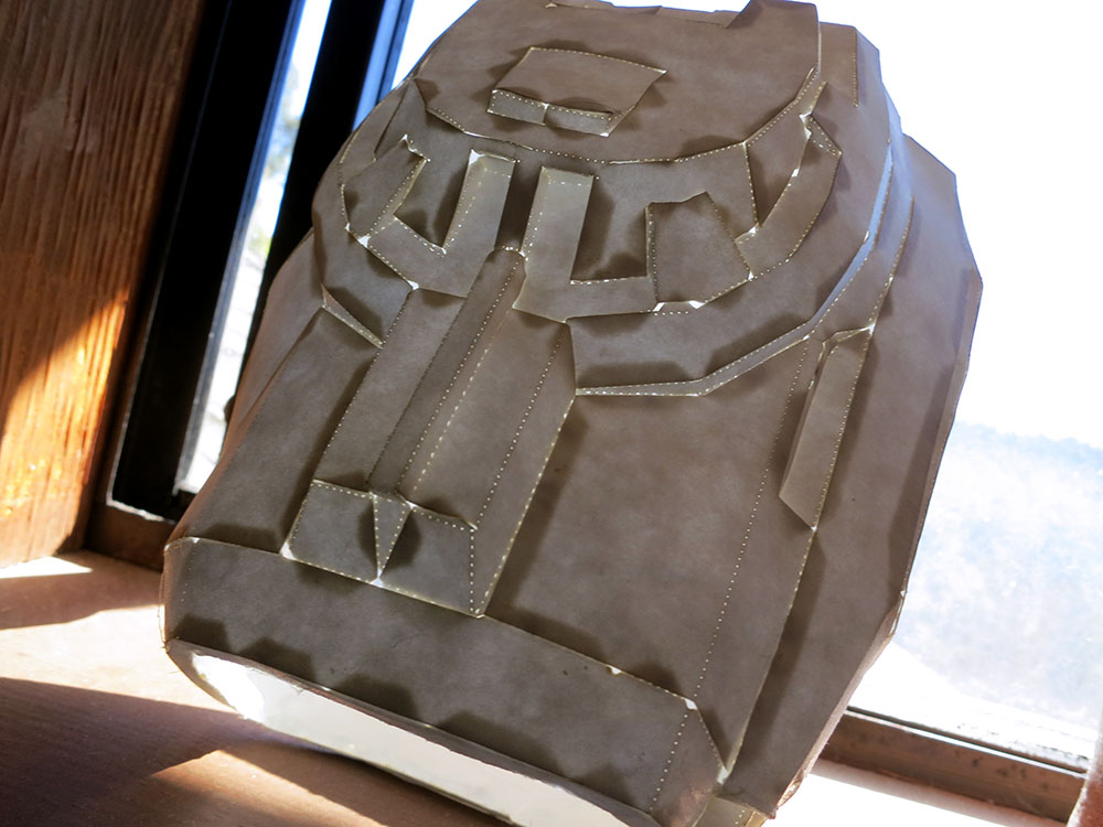
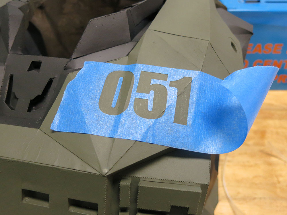
The laser cutting took about 2 minutes for cut lines and 6 minutes for the dotted lines. The cutter is stupid about the short segments in those perforated lines, so it actually cuts them significantly more slowly than the normal cut lines. Laser time was maybe 10 mins per page, including setup and taping after cutting. The torso was 6 sheets, so it took almost a full hour to cut, but I can only imagine the amount of time saved. How long did the gluing take? I spent a weekend gluing up two biceps and a forearm. I had started a new audio book and listened to it while I was working, so I unintentionally timed my gluing. It took 13 hours 45 minutes for those three pieces. They have about 45 segments each.

Bicep Fully Painted
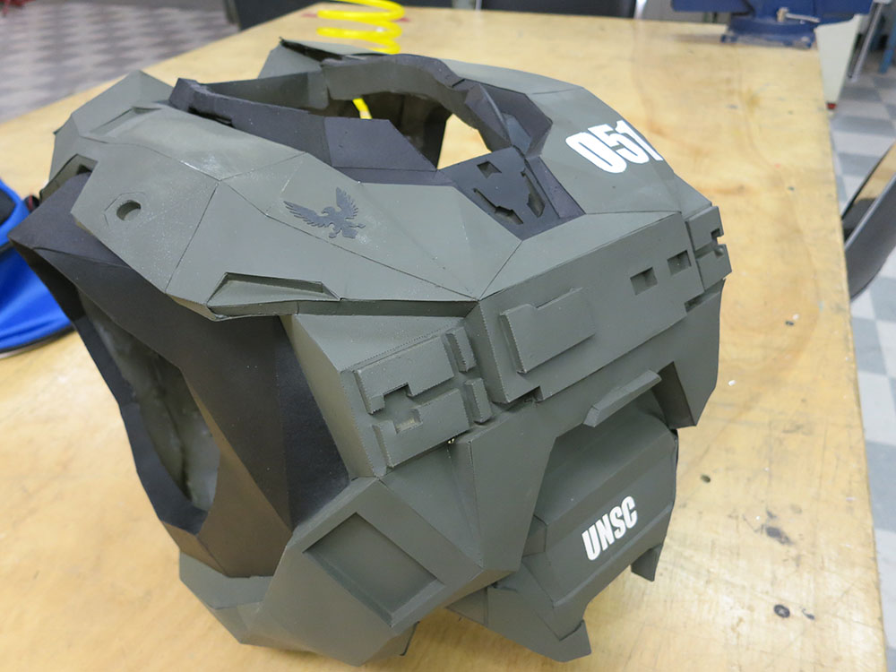
When I started, I told my son I wasn’t making any leg pieces or the helmet. I didn’t have enough time to build a full suit and the helmet and legs seemed like the pieces he wouldn’t be able to wear for trick-or-treating anyway. Partway though the build, he told me he actually wanted to be not just any Halo Spartan, but the Master Chief. I told him I couldn’t swap armor types at that late date, but I could paint it in the Master Chief color scheme. We were joking that maybe instead of a Master Chief he could go as a Halo Master Chef, and he could have a chef’s hat and apron instead of a helmet and leggings. Pioneer loved the idea, and that’s how the Halo Master Chef project was born. After rejecting ideas like the “Gravity Ladle,” we finally decided that the rolling pin was the funniest of the weapon options.

Torso All Glued Just PaperOnce the paper shell was done, I decided to back the paper with hot glue. Many people use fiberglass for strength, but that seemed way too slow, messy, and toxic for something he was going to outgrow in a few months. Hot glue is deeply wonderful for doing this sort of thing. Just squirt it in with the gun and let gravity pull it into an even coating. Keep drizzling more hot glue at the front of the downward sliding wave of glue, and it just works.

Torso Inside

Torso Filled With Hot GlueWhen you have thick glue, it can take several minutes to fully cool and set. This long setting time along with the need to re-enforce all sides of various openings forces you to glue it in stages. You need to let each stage cool before working on the next side. Tilt things so the glue moves the right way and dams up in the places you want. You can also use things like a straight piece of wood to position edges so they cool flat instead of bulging, etc. It’s very quick, especially compared to fiberglass. I was able to hot glue all the arm pieces in a single evening. After that, the parts are quite tough. There was one casualty of this process. After pushing several pounds of glue though my trusty (but cheap) hot glue gun, my impatient squeezing finally drove the heating element right out of the front of the gun. I guess it’s time to try a slightly more upscale gun.

Customized Neck OpeningThe torso is kind of a strange shape, and it was really hard to tell if it was going to be the right scale. I knew I’d have to modify the neck hole because it simply was too narrow for my son’s neck. I did some freehand paper design with card stock to make the neck hole bigger. After that had been re-enforced with hot glue, I had to hold my breath and cut open the entire torso with a hobby knife. I still didn’t know if my son would really be able to get into the torso. I even bought a longer chef’s apron in case he couldn’t get the torso piece on. I was worried I’d have to hack some bigger arm holes or perform other violence to make it work. Thankfully, we were able to get it on him. *phew*

Getting the torso armor off and on was a bit of a squeeze, but it worked. The only down side was that part of the front panel has to flex a bit to be able to open the back, which puts some wrinkle marks on the most visible part of the suit. I hot glued a magnet in the upper corner of the suit to hold that in alignment, and I also added two Velcro straps. I think it would have been nicer to have pairs of rare earth magnets all along the seam, so it all would get held in perfect alignment, but those magnets would need to have some sort of holding ring to give them enough surface area for the glue. I didn’t have time to figure that out or order special magnets, so Velcro was an easy on-hand solution.

I painted all the parts with primer then applied coats of army green. I masked the neck and arm areas of the torso and painted them black. After that, it was time to hand paint a bunch of dirt and grunge and a dry brush silver paint on various high points and projections to make it look as if the original paint had scraped off to show the metal underneath.

laserCutBlueMaskingTapeTorso Masked For NumberstorsoDoneExceptForDetailPaint

I laser cut some blue masking tape so I could spray paint the identifying numbers on the torso. I used 051 which is a nod to my namesake Kurt (Ambrose). I also put a black laser cut UNSC Eagle on. I finished Pioneer’s torso detailing the night before Halloween, and it was all ready to wear to school. I was surprised how well the suit held up. Paint was scraped off all the way down to the paper on some of the joints where the arm pieces rubbed against the torso, but in general it still looked good after a day and a night of candy-fueled revelry. We added a black sock as padding around the neck, but that was pretty much the only game-day alteration. Thankfully, the whole rig is still pretty light. I thought he would be less mobile with that rig on, but it wasn’t that bad. He could even ride in the car and use the seat belt without any problem.

masterChef1masterChef3

masterChef2

masterChef4

masterChefInCockpit

I’m going to mark this one down as a success.  I have a video of the Master Chef looking tough on Halloween Morning.


Getting Printed Circuit Boards Fabricated

Close Up Of Nano And BLEI’ve been making progress on the camera motion rig, but it is a not very portable mass of protoboards, wires, alligator clips, and bench-top power supplies.  It works, but it took me 15 minutes just to move it from one table to another.  At this point in a project, you have a few options. You can solder the components onto some perfboard and direct wire up all the connections.  That’s nice and immediate and makes it fairly rugged, but what you end up with is an ugly one-off board. Another option is to make a printed circuit board.  I’ve been etching them since the days of rub off letters/pads/traces, when I’d spend hours with an Exact-o knife and a rubbing stylus. Then for years, I used various toner transfer methods.  These methods let you print your design out on a laser printer, and then transfer the toner onto a copper clad board.  The toner acts as the resist and you etch away the rest of the copper.   Finally, a process where making the second board was a lot simpler than making the first one.  Still it was a pain because getting super clear transfers is a bit tricky, and aligning a second layer is a pain.  You spend a lot of time touching things up.   On the bright side, you can have the board the very same day.  I’ve been doing this for years, but the price of getting PCB’s made has been dropping and dropping.  So I finally decided to have the PCB’s for the camera control rig commercially made. Bluetooth Breakout Board FootprintI downloaded the free version of Eagle CAD. It lets you design boards with some limitations in terms of size and number of layers, but it seemed like it would work for me and, hey, it’s free.  Jeremy Blum has a nice set of video tutorials about the basics of Eagle CAD. My project is a little strange for a first attempt at a board because it is made up of a number of individual daughter boards.  There’s the Arduino Nano, the Bluetooth Break Out Board, and the stepper motor driver board.  Instead of starting by plopping down standard library components, I had to dive right in the deep end and start defining my own custom components.  Sparkfun has a bunch of good Eagle tutorials, including one that walked me though making my own part.  I spent the entire first evening just making the two missing devices.  That tutorial is really aimed at surface mount devices so I kind of had to wing the though hole part. Stepper Motor Driver FootprintEvery device has a symbol which is what shows up in the schematic, and one or more packages which match the physical shape of the device.  So for example a 555 timer chip has a single schematic symbol, but then can come in a tiny surface mount package, or a much bigger through hole version.  I was so exited when I finally got to the stage of being able to plop down my three main components and wire them together. On the second night I wired up the rest of the schematic.  That would normally be fast, but as you add components you have to always pick exactly which physical component you’re going to use.  It’s not just 100uF Capacitor, it’s a 100uF Capacitor with radial 3.5mm though hole pads and 8mm spacing.  Thankfully I was only using one resistor type, two types of capacitors, and two kinds of connectors.  So it took a while, but not crazy amount of additional time.  I think onece you have sort of built up a arsenal of devices you tend to use in projects that part will be much faster and less painful.

Screen Shot 2014-05-10 at 8.52.03 PM

Final Schematic

By the end of that evening I had wired everything up.  I noticed I still had some unused Arduino pins.  So I added a tri color status led, and a voltage divider so I could monitor the 12 volt supply in case it was being driven from a battery.  That way  I could support a low battery warnings, etc.  I also pushed the last few pins out to an aux port so I could add things like an external trigger button or jog knob later if needed.  Then I was ready to take a stab at routing the board.

Screen Shot 2014-05-10 at 9.24.56 PM

Footprint Problems

It was then that I saw various problems with my hand built parts.  I’d manually put holes though the pads which was redundant and was also causing an exclusion zone around those pins.  My ground plane was avoiding those pins like the plage.   Heck even the Nano part lib I’d downloaded had to have the corner dill holes removed. Also my extensive naming of things had really cluttered up my silk screen layer, and Eagle’s Smash Part command which lets you move the name/value around independently wouldn’t let me move those silk screens around.  *sigh* Screen Shot 2014-05-10 at 8.54.52 PMThe third night I spent reworking my custom devices, beefing up the various power lines,  fiddling around with labels, adding holes for mounting screws, and being generally anal retentive.  I spent a while trying to use Net Classes so the auto router would beef up the supply lines on it’s own, but for some reason it just was not having any effect.  I used the RIPUP; command a lot during that period.  It rips up all the routing on the board.  In the end there were only a few short runs that needed to be really beefy so I just routed them by hand. Ok so the board was mostly ready to go.  Now I had to get the thing built.  You can get Eagle to export GERBER files which define the various layers, have separate files for the layers, holes, solder masks, etc.  All the files need to have the right names and file extensions.  It’s all very fiddly.  Thankfully there are CAM job files you can download that will take various layers in Eagle and spit out a pile of properly named GERBER files.  So it’s a mostly automated process.   Then you zip those files into a single file and you’re ready to try sending them to some board manufacturers.  Jeremy Blum’s third video goes over doing this, and he has a Job file you can use.  His third video has a lot of tedious “putting together a bill of materials” section.  That’s probably the only really bouring thing in his otherwise awesome videos.  If you already know how to select parts (which you practially had to do to decide on parts for your layout) you can skip the middle third of that video. Lady Ada has a page comparing the various manufacturers. OSH Park Board PreviewI decided to try OSH Park first.  Just because I liked the sound of $5 a square inch for three boards and free shipping.  For small boards that seemed ideal.  It turned out all that fiddling around making GERBER files and CAM job messiness was totally unnecessary.  OSH Park takes Eagle board files, and a few seconds later you’re looking at beautifully rendered views of the various layers of your board.  Their boards have both top and bottom silk screens and are purple with gold plated pads.  So swanky.  They quoted me $29 for three boards.  I was so swept away by the simplicity and the nice looking layers that I just fired it off.   I was so excited.  A few minutes later I realized I hadn’t done the one test I had really wanted to do.  Printing out a scale version of the pads and making sure I had all the spacings correct on my home brew parts.  It was late at night at this point but I just HAD to know.   I wasn’t going to sleep well wondering if I’d have to wait 12 days to get 3 pieces of unusable purple and gold junk. Sadly my laptop isn’t connected to a printer so I tried exporting to .pdf and emailing that to myself so I could print  in from our desktop machine.   When I printed it out the sizes where all screwed up.  Either everything was off, or the scale was getting fiddled.  Googling around it sounded like others were having scale problems with pdf’s.  So I saved the file as postscript.  Sent that to myself and then I had to figure out how to send a .ps file to a postscript printer from Windows 7.  You’d think that would be trivial, but you’d be wrong.  I ended up having to install both ghostscript and the gsview postscript viewer before I could finally print  it out.   By then it was well past 1am, but I just HAD to know.  This time it printed out properly.  The pin headers had the right spacing the Nano matched, but horror or horrors the stepper motor driver’s two rows of pins where one step too close together!

Stop the presses!

Thankfully OSH Park batches your job up with a bunch of others so I was able to get them to cancel my board without a hickup.  I’m sure I wasn’t making my best first impression with them.  Oops.  I got up early and reworked that part’s foot print for the second time.  I hand re-routed the power lines again, and soon  I was back looking at the awesome purple eye candy. Screen Shot 2014-05-10 at 8.57.53 PMWould I hit the Buy Button this time?  No.  This time I was a bit more catihous. I noticed that on the actual CAM output of the board they were cutting the ground planes into strips.  That probably helps cut down on eddy current noise or something, but there were a few places where I was depending on that plane to conduct the full motor current.  I decided to go back and direct draw a few fat lines in those areas.   Also there was a place where an important pad had copper removed around the corners to make it easier to solder.  Soldering to a full copper plane is a pain since it skins so much heat.   For this one important pad there were only two small tabs connecting it to the ground plane. I fattened that one up to .056mm hopefully striking a better balance between solderablity and current. New Wider Stance and Wide PadsI also realized that OSH Park includes a bottom silk screen that I hadn’t used at all because I didn’t want to pay for that.   I quickly moved a few notations down to the bottom just so the board would look nicer.  Bottom silk screens are nice because that’s often where you’re poking around with probes trying to trouble shoot things.  Well at least for through hole projects.  Now finally when I was scrutinizing those purple and gold lovelies rendered on the OSH Park site I decided to pull the pin.  There are two capacitor pads that I wish were a bit bigger.  I think they may be hard to solder, but I declare it good enough.  I also experimented with converting the stepper board from normal round pads to the old style wide pads.  This way I can compare solderability. That day we were going to a friends birthday party and Cheryl and I both wore purple and gold to celebrate my first board send off. Now I have to wait 12 days for the boards to show up.  What the heck will I do?  I guess I can try some more time lapses and maybe start work on the enclosure.  Apparently I’m also doing a  blog post.  So far I’ve been very happy with OSH Park.  Their upload and verification stuff is slick and simple.  Since I’m already using Eagle it really could not be easier.  They also let me cancel my one rouge order.  I tried uploading my project to Seeed Studio and their site seemed to be telling me that it would be $9 for 10 boards which has to be wrong but there was no detailed feedback about the order and I couldn’t tell what was wrong.  For prototyping I think OSH Park is worth it.  If  I get to a point where I want to make more than 3 boards I’ll have to try someone else.  Now I just have to hope I haven’t screwed anything else up.  Are the 12 days over yet!?

Make Time Lapse Candle Videos

Timing a Birthday CandleWhile waiting for my project’s Printed Circuit Boards to arrive, I decided I should try shooting some more time lapses.  I won’t be able to design the iPhone software until I get some more experience.  I wanted to figure out some sort of time lapse that wasn’t crazy long.  That way I wouldn’t have to worry as much about ambient light changes, and I could try out different things quickly. I picked up a pack of birthday candles at the super market.  How long does it take one of those puppies to burn down?

I timed one, and it came in around 15 minutes.  Perfect.  Now all I needed was a better background.  As nice as peg board and cobwebs are, they weren’t the best back drop for my first time lapse, so this time I went that extra mile. I put a rusty steel plate behind the scene, but I still had to cover the base of a lamp. I decided to use a lovely wooden cutting board that my uncle had made for us. Alright, the stage is set. I completed my first candle time lapse.  That one went ok.  I was pleased by how the spirals on the candle sides make them look a bit like the tops are spinning down.

Blue Candle Lost SequenceThe one downside to shooting time lapses involving fire is that you must have a fire extinguisher handy and keep an eye on them the whole time.  None of this “set it off and go to bed” crystal growing luxury. One mistake I made was that I lit the candle with a match and accidentally clonked the candle while I was doing it.  For my next shot, I wanted to set up a bunch of candles and light them incrementally.  I rushed to the corner store and bought one of those butane BBQ lighters.  Now I was ready.  My first shot had been a bit short because the candle didn’t burn all the way down before the preprogrammed time lapse ended.  I guess my 15 minute test included a little bit of me blowing on the candle, which really shortens the burning time because it melts extra wax.  Also, this time I was going to be lighting them incrementally.  Best not to have it run too short, so I switched to a 28-minute duration.  I used the stopwatch on my phone so I could light the candles in 30-second increments.

I really like the idea of performance time lapse.  It’s kind of fun dodging in and out of scene between camera shots.  After 28 minutes of watching the candles burn, I rushed inside to squeeze all those stills into a movie.  OH NO!  This time there were no frames on the SD card. I’d wasted the entire shoot. What happened?  I still don’t really know. I’m using CHDK so my camera now has about 8 zillion tiny menu options, and eventually I just reset everything and re-enabled the USB remote feature.  Then it worked again.  It was so weird because during the entire shoot it was acting as if it were taking pictures.  Now I know to really watch the “remaining frames” number and make sure it’s actually going down.

Red Candle Disaster Waiting to UnfoldI did two more shots: a green one and a red one.   For the last shot, I  propped the camera rig up with some clothes pins on top of an empty cardboard box so I could have a shot looking down on the candles.

The Mystical Garden Poltergeist Wreaks Havoc

I sat with the camera until all the candles were out, and then I left.  When I came back, I found that the camera had flopped forward and done a face plant on the rocks!  In a panic, I tested the camera, but it seemed to be working.  While looking at the time lapse frames, I noticed that at the frame where everything went wrong the words “Mystical Garden” were eerily smeared across the rock.  Was the ghost of my previous time lapse jealously haunting the set?  No, but almost as miraculously, the camera shutter had been open during the exact moment of  collapse and had taken a smeary photo of the nearby box my crystal growing set had come in!

fallingCameraPhoto


I hear by swear off the Cardboard Box and Clothes Pin Mounting System.  Time to build a tripod mount and lay this Mystical Garden to rest. You can see all the candle time lapses here.

Building an Arduino based Motorized Camera Rig

I’ve always wanted to make a time lapse video. It’s like building a machine to catapult forward in time.  What could be more fun?  I really feel like the best time lapse videos integrate camera motion to give the scene an additional compelling dimension. I spent a couple of evenings building a quick and dirty motorized camera slide from a dead inkjet printer. It was a failure.  It was unable to produce the slow steady motion needed for video, much less the kind of control needed for time lapse.  I started to think about what a serious system with substantial time investment would have.  It could be bigger and have at least two-axis camera motion.  It would need a bunch of software with some way of key-framing the camera motion, maybe an LCD display, maybe a pendant control for stepping/snapping frames without jiggling the camera.  What else?  A way to power and auto-trigger the camera for time lapse.  All in all a much, MUCH bigger project.  OK, if that’s the end goal, what’s a good first step? I’m always wary of  physically big projects. As the size goes up, costs go up. Big projects are harder to get into/out of the car, take up more workbench space, and ultimately collect dust in a bigger way.   If I can fit a project into a single project box, life is simpler.

Bigger Motor ControllerSo instead of embarking on a large two- or three-axis rig, I decided to build a very small one-axis rig.  Heck, I already had a small one-axis slide.  This way I could get my feet wet with the software, LCD, motor controllers, and all the other fun stuff, but without as much schlepping. A friend of mine pointed out that a little motorized stage like that could also be used for focus stacking, and he’d been wanting to build a focus stacking rig.   He sent me little linear slide with a stepper motor drive and a tiny ball screw.  I’d never seen a ball screw that small!   It was sweet!  I poked around on Amazon and ordered a A4988-based stepper motor driver the size of a postage stamp.  They were cheap, small, and the data sheet made them sound like they were doing a decent job with the microstepping, which might be useful for very precise focus stacking.  I used to build stepper motor drivers out of discrete components, but it’s unbelievable what you can get these days for not much money. I’ve been itching to try some of the pre-made ones out, so I ordered the stepper motor and a much bigger driver board based on the TB6560, mostly because I was having trouble convincing myself that a driver without a heat sink was really going to be able to do the job. And even the big one was cheap.  It was less than $17,  including two-day shipping to my door. I’d also been wanting to play with some of these cheap LCD displays I see around, so I ordered a 4-line 20-character blue one that Amazon Primed its way to my house for $16. I ordered the blue one because a green-and-black LCD was going to make the project look like it was from the early 90’s.  I ordered one that had an I2C daughter board because I wasn’t sure how many IO pins this project was going to need, and I didn’t really want to burn half of them driving the display. When the display came, I was bummed that they’d shipped me the green and black version, not the blue one!   I set my time machine for the early 90’s and kept moving.  I wired up the display to an Arduino Uno.  I downloaded the Arduino IDE and a library to drive the display.  I wired it up like this:

Screen Shot 2014-04-23 at 8.44.48 PM

Then I ran this exciting bit of code.

#include <Wire.h> 
#include <LiquidCrystal_I2C.h>

//Addr: 0x3F, 20 chars & 4 lines
LiquidCrystal_I2C lcd(0x3F,20,4);

void setup()
{
 lcd.init(); 
 lcd.backlight();
 lcd.setCursor(0, 0);
 lcd.print("Hello World");
}

void loop()
{
}

Two DisplaysThankfully, it just worked.  The text was super crisp and readable.

I was still a bit bummed about the color, so I decided to roll the dice and try ordering the blue display again.  I’d be able to compare the two colors side-by-side and see which one I liked best. This time I did get the blue one. It worked and was crisp and clear.  Our eyes don’t like focusing on dark blue things though, and if I had to be brutally honest I’d have to say that the green display was more readable.  I decided to switch to the blue one anyway.

Special CharactersI wrote a little program to page through all 256 characters that could be sent to the display to see what sorts of special characters might be available.  There were a few useful ones like left and right arrows, the deg symbol, and a solid block character which I might actually use in my interface.

The next step was to put the various parts I was thinking about using together to visualize how things were going to fit.

Component Layout And Sizing

I was originally going to mount everything to the side of the motorized stage so I could cut down on external wiring.  I could even put the end-of-travel sensors inside the project box.  But it was starting to look 10 pounds of project in a 5-lb bag.

The project box was big, and it was going to have to be right under the camera or using it would be uncomfortable and trying to manipulating it would jiggle the camera.  Those issues seemed like deal breakers.  The next plan was to put the control box at some distance from the motor and make a separate control pendant that could plug in.  I’d need OK and Cancel buttons and some sort of spring-loaded pot for jog control.

Remote Jog WheelI went poking around at the local surplus store and scored a VCR remote with a nice spring-loaded jog wheel.  It even had two buttons inside the wheel, so I thought my control pendant problems where over.  I’d wire up the jog wheel/buttons through a phone connector to the main control box, and I’d be all set.  However, when I dissected the remote, I found that the jog wheel was not a pot.  It had 3 digital pins providing gray code position info.  That meant only a few jog speeds in each direction, and it meant I’d need more lines than a standard phone cord.  Back to square one.

Spring Return PotI decided to take a stab at adding my own spring to a pot to make a “return to center” jog controller.  I drilled a hole through the pot’s shaft and bent up a spring.  It worked. After some fiddling, I was able to make it control the motion of the slide.  It had a really sloppy feel to it. The center was always just kind of approximate, and it was harder to turn in one direction than the other.  Kind of a cruddy experience compared to the feel of the remote’s nice jog wheel.  I decided to punt for a while and work on other parts of the project.

End of Travel SensorsI wired up the end-of-travel sensors.  I was using IR gap sensors for a no-contact way of measuring the travel.  Now that the sensors couldn’t be mounted inside the project box, I decided to make them fit inside a bit of metal wiremold that I had lying around.  I used some Bondo to hold the sensors at the correct height and support a phone jack at the end so the sensors could be easily connected up.

This was by far the most annoying part of the entire build.  The phone jacks turned out to be back-stabbing fiends.  Fitting everything in the wiremold was annoying, and I had a wire tear out when I was closing it up.  Then the sensors weren’t working, so I ripped everything apart trying to figure out why. I had accidentally grabbed a two-conductor phone cord even though I’d  purchased a 4-conductor one. Then when I finally figured that out, I failed to realize that when using phone connectors, the wires get flipped from left to right so red on one end becomes green on the other, and black becomes yellow.  *Smack Forehead*  After I figured that out, I thought I was home free, but it still didn’t work.  I finally traced the problem to a poorly designed jack where the connector could clip in, but was still not fully seated and wasn’t making contact.  After that got resolved, everything was fine. But I’d burned an entire afternoon trying to run 4 wires a few feet.

Quick Release Plate MountedI got a super cheap quick-release plate.  When I was taking it out of the packaging, a spring and pin fell right out of the bottom.  I deemed them to be unnecessary and threw them out.  Then I noticed that  the cam lock tends to slowly unscrew and the screw can’t actually be tightened properly without making the cam hard to turn.   A dab of Loctite could solve that.  Hey, it was cheap!  My only regret is that I wasn’t able to mount it so the cam stuck out the same side as the wiremold.  This would have made the whole thing more compact left to right, but that might have required tapping some blind holes, and this way around it was simple to mount.  Just a 1/4-20 though an already existing hole in the carriage.

LCD Rig Wire MessI had all this wired up to an Arduino Nano.  It could jog the motor when I twisted the pot, and it could read the end-of-travel sensors.  Next was to start designing some UI for the LCD.  I played around with being able to highlight various menu options by quickly toggling the solid block character behind them, etc.  It all seemed doable, but it was kind of tedious Arduino development. I kept thinking “How is this going to scale up for multi-axis key frame animation craziness?”

 Massive Feature Creep Occurs

It was then that I noticed Bluetooth LE boards for the Arduino.  Could I control my whole rig from an iPhone app? I could ditch the LCD, buttons, pendants, and all the associated wires and connectors.  I could make the project box smaller.  I could write an iPhone app to do the interface heavy lifting, and I’d only have to do a moderate amount of stuff on the Arduino end of things.  No more planning out of awkward LCD interfaces.  Plus, it just sounded fun!

Blue Tooth ConnectedSo I ordered one of the boards, and I was off to the races. Adafruit’s page about wiring up the board is very clear, and I hooked up an Arduino UNO just to try it out.  I was able to get their UART echo communication going right away.  Simple, Pimple.
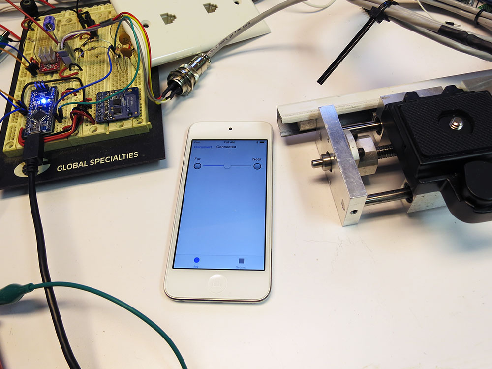
The next test would be to write my own program to establish the Bluetooth communications and see if I could use a slider to jog the motor.  I wanted to test the latency and to see if stepper motor switching noise would affect the communications.

The great thing about Bluetooth LE is that you don’t need any special licensing.  I spent one of my precious Wednesday nights ripping the com parts out of the Adafruit example and sticking them into my own simple app.  The app just had a connect/disconnect button, a connection status indicator, and two end-of-travel indicators. The communication is only 9600 baud, so I made a special jog loop the Arduino could go into where the phone would keep sending single bytes of  jog slider info, and a 0 would indicate that the jog portion was done and go back to the main loop.

The very first version wasn’t wired to anything. It would just indicate end-of-travel limits having been reached if you slid the slider close to the end of its travel path.  After tracking down an issue with a rough signed char, I got it working. The latency was quite low.

Jog Actually WorkingNext up: rewire the Nano to remove the LCD/knob and wire in the Bluetooth LE board.  Then I’d be able to jog an actual motor. I powered it up and could hear the motor making some ticking sounds, but jogging wasn’t working.  I went to hook up the scope and bumped the alligator clip that was providing motor power.  It touched something on the board, and the Arduino’s LED’s went out.  Yup, I’d fried the Nano.  Ouch. Oh dear. Had I fried the USB port on my computer?  Apparently not. *phew* No need to panic.   I did not, however, have a spare Nano on hand.  Trying out the jogging was going to have to wait until next week.

Jog On OscilloscopeIn the mean time, I rewired some parts of the protoboard to make it a bit less hairy.  I don’t want accidental short circuits killing things, but I also don’t like clipping the leads on resistors and caps.  When the replacement Nano came, I decided to only connect motor power after I was reasonably sure the other things were working.  I  used the oscilloscope to see if the Nano was producing the expected step pulse trains.

Yup, that seemed to be working.  With some trepidation, I decided to try and hook up motor power again.   Nothing burned out, and it worked!  Next I needed to see if the limit switches worked. I jogged the stage all the way down to the end, and one of my limit indicators on the iPhone started flickering like crazy. But it was the wrong indicator. I swapped near/far sensors and added some software switch debouncing.  The slow linear ramp of the limit sensor was producing a lot of noise when it got close to the logic level boundary.  I’d love to run it into a nice Schmitt Triggered gate.  That would keep the software nice and clean, but if I was going to have PCBs made, it would add area and expense.

I could have made them go-to-analog inputs and just used two thresholds.  That’s probably what I should have done, but  stepping at 1/16 of a step was putting me at 54400 steps per inch, which was really taxing the powers of the accellStepper library and I didn’t want to add much to my inner loop.  That’s probably silly of me and adding two analog reads to my loop wouldn’t matter. Instead, I did digital reads and required a large number of matching consecutive answers before alerting the iPhone. Probably over complicating the code since the real bottleneck in accellStepper is probably its use of millis() not a couple of  analog reads.
Camera On RigNext up was to install CHDK on my camera and see if I could manage to use a USB cable to act as a remote shutter switch.  CHDK runs on various Canon cameras and lets them do things they normally couldn’t.  My camera (a Canon S100) didn’t have a way of remote triggering, so I had to hack it with CHDK  to do that.  You have to make a special bootable SD card.  I used a tool called STICK to analyze a photo taken by my camera, determine the exact firmware in the camera, and download and format a bootable SD card.   This made setting it up simple.  Then I went through a maze of  menus to turn on remote shuttering. I wired one of the Nano’s output pins to my camera’s USB port and wrote a snippet of code to take a picture. It worked! Right now I hold a line high for 1 second, and then it takes a photo when the line goes low. I haven’t tried running a shorter cycle.  Maybe with manual focus/metering it could take photos more quickly.  I haven’t tried.

timeLapseStagetimeLapseSetup

I had motion, I had photo taking. It was time to try and do a time lapse with this rig. I took it over to my son’s Lego studio area and set up a magic crystal garden I’d purchased online.  I used fun-tack and clothespins to aim the rig, plunked an old calendar photo of clouds in the background, and we were almost ready to go.  I set all the camera settings to manual. Then I set the code to move though the system’s full range of motion over 10 hours, taking one frame every 2 minutes for a total film length of 10 seconds.

I waited until it was dark, and I fired off the time lapse.  It felt like Christmas Eve,  and I didn’t know if Santa was going to leave me a time-travel movie or a lump of coal. I told the kids we couldn’t go into the garage for 10 hours. In the morning, I went out to see what had happened.   The first thing I noticed was that one of the big chunks of foam I’d taped up over the garage windows had fallen down during the night.   Oh, oh.  Still, the crystals were fully grown and there were 300 photos on the camera, so it was time to try and play them as a movie.   Unfortunately, iMovie only lets you specify still frames down to 0.1 seconds in length, so you can’t really make a 1/30 of a second one-frame-per-image movie.  Argh!  Photoshop can do it, but that requires loading all the frames into layers. On my machine, loading in 300 big 3000×4000 pixel images was taking for-ev-er.   Finally, I just downloaded some freeware frame encoding tool and used that to build my time lapse.  Then I could use iMovie to add title, fiddle with the sound, etc.  By 11am, I’d finally managed to unwrap My First Time Lapse.  It was over-exposed and didn’t have great focus, but the kids thought it was cool.  Success!


crystalsFinalState