Building a Motorized Camera Slide from a Dead Inkjet Printer

PhotoJoJo sent me an ad for a small camera slide.  It was kind of a lot of money, and wasn’t even motorized.   I’ve been taking videos of projects and thought that a little motorized camera slide might be a nice way to spice up those kinds of videos.  I  remembered we still had a dead inkjet printer left over from the kids’ “Take  Stuff Apart Day” that we’d done a few months ago.  Inkjets have a linear motion slide inside.  I thought, “Wouldn’t it be cool if you could make a camera slide with basically just the parts from a printer?”

Motor ControllerI didn’t want to have complex control software, and I wanted it to be mostly made from the printer. In the end, I spent about 4 evenings hacking up something.   There are lots of cheap motor controllers out there, so I squashed my initial instinct to hack up a speed controller out of bits from my junk drawer.  I instead decided to act like an adult and order one of these.   With free amazon prime shipping I could have it in two days for under $10.  I’d probably end up spending more on perfboard and components building a  home-brew driver. Plus, if this project was  a bust, there would be plenty of other uses for the driver board since it could drive a much bigger motor than the one in the printer.


Micro Switches
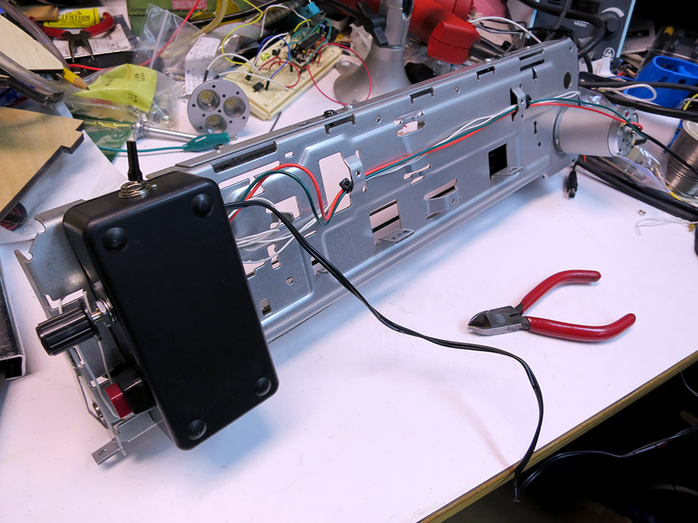
I scrounged up some micro-switches and a wall wart to power the rig.  I also ended up buying a switch and a project box from RadioShack.  So the total bill for this project was about $20.  I even (mostly) used wire that was taken from the printer.  I really wanted this project to be simple to do in the hopes that other folks could build one.   The interface was fun to design because it’s entirely electro-mechanical except for the speed controller.

Schematic 
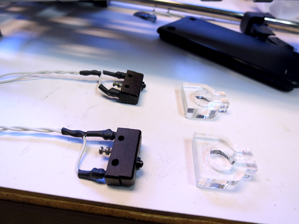
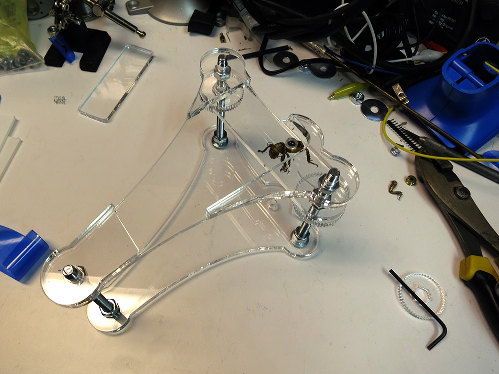
It was fun to design an interface that didn’t have any software but was still nice to use.  I had a direction switch that you could push in the direction you wanted the slide to move, a launch button that would start the stage moving, and two end-of-travel microswitches.  It was fairly complex behavior from a minimal amount of wiring. I was really satisfied with how that turned out.


End Of Travel Switch
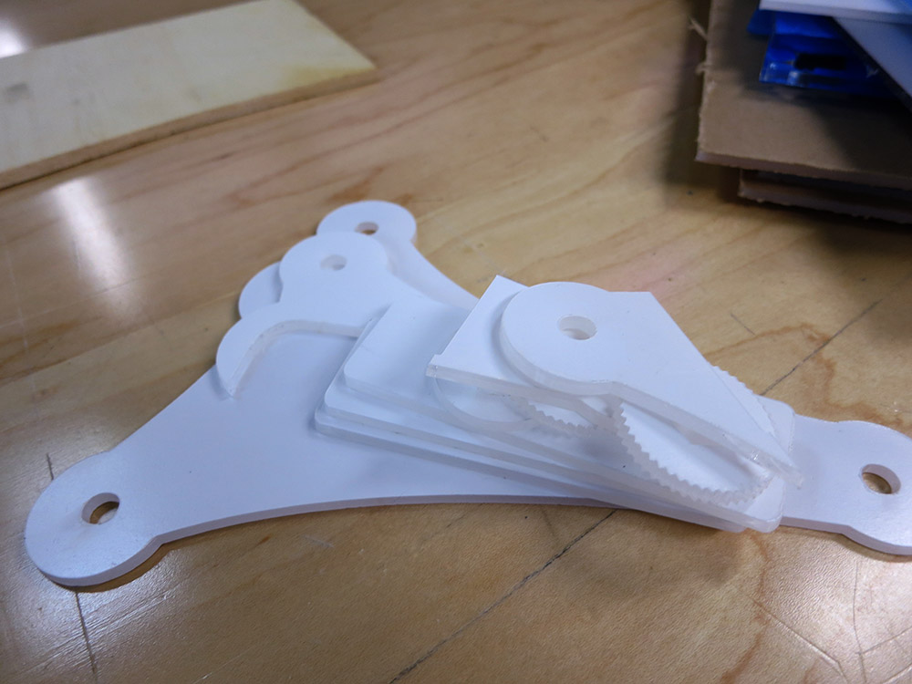
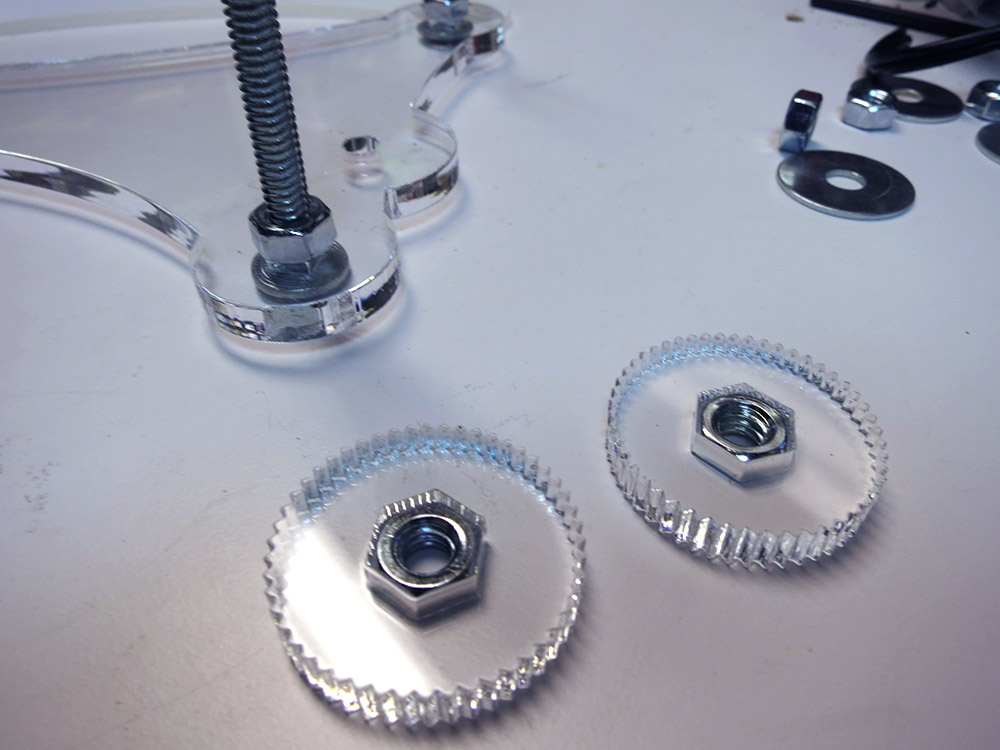
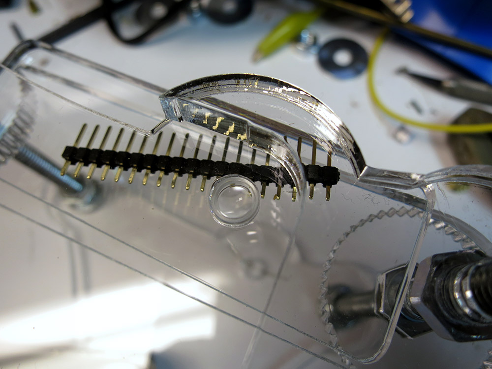
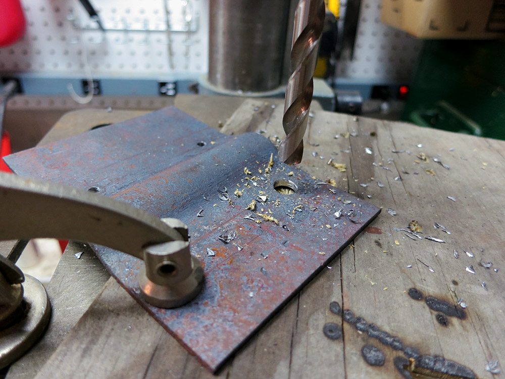
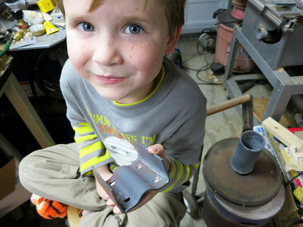
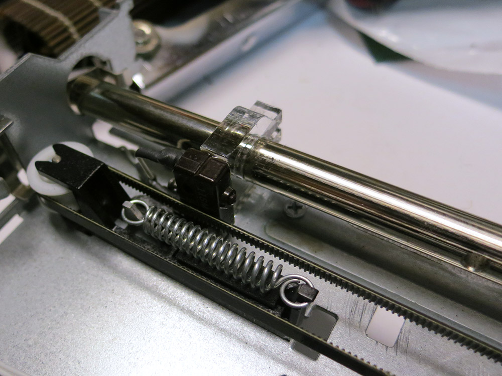
I laser-cut some mounts for the end-of-travel switches so they could be mounted right on the rod that the carriage travels along.  The mounts allow the switches to slide along the rod to position where the camera motion should stop.

Probably the single most time-consuming thing was hacking down the carriage.  I used a cutting disc on my mototool to hack the carriage down to a roughly flat area and then used some Bondo/black spray paint to make it look like a nice, flat surface.  I also stuck a short 1/4-20 screw up though the center to mount the camera on.

I was planning on mounting my Cannon S100 to the slide.  It’s light, so the whole rig didn’t have to be super strong.  Luckily, I happened to have a ball-and-socket camera mount sitting around from an old project, so I hooked that up to the screw on the carriage.

Camera Slide Top View  Camera Slide Bottom View

At this point I realized that for a camera slide this small, most of the usable camera motion is VERY slow motion, and the printer’s motor was just not up to the task when running open loop.  If I salvaged the position encoder and hooked up an Arduino as a controller, I probably could have managed to get very nice motion of of the rig, but since the goal was a one-evening super easy/cheap hack, it was a fail.  Putting a gear-head motor in there would also have worked, but also violated the cheap and easy premise of the build.  Here’s a video of the final result.

cameraSlideDone

I wouldn’t be surprised if there’s another camera slider project in my future.  This time with more motors and software.   This was a great learning experience, and as the Lego Guy said, it’s time to “Keep Tinkering!”

Making an iPhone Microscope

Microscope Parts After CuttingThe other day someone sent me a link to an instructable about using your smart phone as a microscope.  It uses a laser pointer lens, and I knew I had one of those laser pointers at home in the junk drawer.  Its batteries were dead, and its lens could be repurposed.  I had plenty of scrap acrylic around, and I quickly illustratored up the parts for the microscope.

I have an iPhone 4s. I looked up the camera geometry and position of the lens because I wanted to make it super easy to flop my camera down and take some macro photos.  The instructable uses wing nuts, but I thought it would be nicer to have large straight knurled dials to move the focusing stage up and down. I cut out a few dials that would go around the 1/4-20 nuts.

Gluing On The LatheI used JB-Quick to glue the nuts in, and I glued them using the lathe to ensure that the discs were fairly plumb with the bolt.  After gluing, I peeled off the blue protective plastic. I wanted to make sure the specimen slide would be able to ride smoothly on the two nuts.

Microscope Stage Focus NutsThat was pretty much it in terms of assembly trickiness; the rest is just bolted together.  I originally had cut out some acrylic discs to put around the carriage bolt heads, but I decided it looked nicer to leave those out.  I guess you could just put some stick-on rubber feet on the bolt heads if you were really worried about scratching up the table.

I did  a couple of test cuts to get the exact diameter hole needed to hold the lens.  The slightly cone-shaped laser-cut hole is perfect for pushing a lens down into.  I have three pieces of plastic that align the camera.  Right now they’re just bolted on. I guess if I wanted to I could make sure everything was in a really good position and then put a drip of solvent to glue the guides down.  So far I haven’t bothered.

Microscope Assembly Begins  Lens Assembly Close Up

Then it was time to try it out!  First I tried looking at a strip of pins.  Not really very exiting. What else could I look at?   I remembered earlier that day I’d seen the husk of a great big Jerusalem cricket in the the corner of the garage.  I went and snagged it and had a look.

iPhone Taking A Picture  MicroScope With Bug

iPhone On MicroscopeThe rig worked reasonably well.   Lens alignment was quite good, and the stage was easy to slide up and down with the nuts.  The bolts don’t make the best sliding surface, so moving the slide up is smooth, but sending it back down is a “spin the nuts down and then manually press the stage down” affair.  Not optimal, but I was worried about making those stage holes too big and having problems with the stage moving around laterally, which would be worse for trying to do focus stacking.  Frankly, I like the non-focus-stacked images a bit better, but with some practice I might get better results.

Bug Leg Closeup  bugFootWithFocusStacking

Is that a photo of delicious king crab?  No.  That’s a bug’s ankle.  That first photo is just a photo.  In the second one, I took a number of photos moving the stage up a little between photos.  You can touch and hold your finger on the iPhone to lock focus and exposure so you can do this without the phone screwing things up.  Then I imported all the photos into Photoshop, and I had it take a stab at merging the layers using the most detailed areas of each photo.

Bug Thorax Focus StackHere you can see a much deeper photo of the thorax.  I have yet to get super great results with the stacking. Photoshop often screws up the alignment of the photos, and I have to turn off some of the layers.  You can see some banding of sharp and blurry near the edges of the photo.   Those were formed by layers that Photoshop failed to align, and I had to just turn those off.  Sorry the photos are kind of gross.  That bug was just the most interesting thing I happened to have on hand.

I also fished a quarter out of my pocket.   I thought about trying to make a giant panorama of the quarter since it’s kind of flat and didn’t need any focus stacking tricks, but the shiny metal surface is very reflective and viewpoint-dependent, so it probably wouldn’t stitch together very well.   There’s also a photo of a blown halogen bulb filament.

quarter  brokenFillement

Here’s the final illustrator file.  You’ll have to do the kerf compensation for your laser.  Also you’ll have to adjust the lens hole to fit your lens.   I cut a series of holes in the scrap parts of the 1/8″ sheet until I got a good match.  Remember this design sized for an iPhone 4.  I used 4″ carriage bolts just like in the instructable.  If you make one of these, send me a picture!

Making Glamdring The Foe Hammer

Sword SketchPioneer wanted to be Gandalf the White for Halloween this year.   Personally, I wouldn’t have chosen white for a costume that was sure to be grubby three minutes after it was put on, but Gandalf the White still had a long and difficult journey ahead of him  so a few wrinkles and stains would fit right in.   Pioneer had already selected a staff, but I wanted to try laser-cutting his sword.  I’d been working hard finishing the iPad version of our app, so I was getting started on Halloween a bit late.   The sword seemed like any easy first piece, so I snagged some plywood and a scrap piece of wooden molding and went to work.   I got out the bag of leather scraps that I’d gotten from a coworker in trade for one of my wooden puppy dogs.  I figured maybe I could cut a leather spiral or strips to form the grip on the hilt of the sword.

I had reserved the latest possible slot on the laser from 10:30pm to 11:30pm, and my plan was to design the sword in the time between getting out of work and the start of my laser time.  We’d been getting the final cut of our iPad app ready to send to Apple, and I ended up working until 7, but finally I shifted gears and started frantic work on the sword.  I did a quick sketch that I liked, and I started designing the sword in Illustrator.  I noticed that the leather scraps I had were all pretty small, so a big spiral of leather wasn’t going to be possible. I decided instead to cut out a lot of oval leather pieces and stack them to form the handle.

The laser bed is 24″x18″, so I had the choice of making a really stubby sword or doing something tricky.  I decided to cut the blade of the sword on the diagonal in the machine for maximum length, and then make the handle/blade guard out of another piece.   I had some really thin pieces of wood that I sandwiched on either side of the joint to give it strength, and add the runes for Glamdring to the sword.   This was going to be a one-night build, so I had to abandon any ideas of making the sword glow, etc.

Laser Cut Sword PiecesThe big problem with putting material in the laser on the diagonal is alignment.   I cut the outline of my piece of wood molding out of a scrap of cardboard, and used that as an alignment jig.  It worked fine for the basic cutting, but when I had to flip the wood over and etch the central fuller on the other side of the blade, the blade was off by a few degrees and the detail was clearly not super centered.   If I had it to do again, I’d have the blade oriented the other way around so being off by a few degrees would hardly be noticeable.

I used shape interpolation in illustrator to make the 35 pieces I wanted to cut out of the leather.   It was  fiddly and time consuming to position the pieces on my various leather scraps.   I used a pencil to number the pieces so I could stack them from large to small without mixing them up.   Then I cut the parts for the hilt out of my piece of plywood.  In the half hour between the end of my laser slot and TechShop’s midnight closing time, I went and used the big belt sander  to sand some profiles onto the blade.  Kind of a freehand grid to shape.  I didn’t want the thing to actually be sharp, but it gave the blade a more realistic shape, and kept it from just being a flat cutout.

Then I went home and glued it up.  I wanted to be able to let the glue set up over night.

Glamdring Runes and HiltswordWithNoHilt

As I was assembling the blade, I realized that I liked the look of it much better without the piece that had the runes on it.   Leaving it out makes the blade to hilt connection a lot weaker, but I just liked the look of the blade without that stuff on there. Also, the little cutouts on the ends of the cross guard looked kind of cheesy, so I just left the rune piece out entirely.  The sword hasn’t broken yet, so I guess it was the right call.

Stacking the Leather to make the hilt I woke up early the next morning and glued the 35 leather pieces together to make the hilt.  Because I was using leather scrap of different thicknesses, not all of the pieces had been cut out cleanly by the laser, so I had to tear some of them free.  They slid onto the hilt, and the locking mechanism I designed into the butt of the hilt clamped the discs in nicely. I probably didn’t even need the glue.  One problem with the leather pieces I had torn free had a lot of wispy strands at the edges.  This made the handle rather shaggy.  What to do?   I knew that trimming them would be a pain, so I simply assembled them as is, and used a propane torch to burn the little strands off when I was  done.

Sword Handle Leather DiscsIt worked great!  The strands would get hot and burn off long before the surface itself got hot enough to burn, and it was super fast.   I’ll have to remember that trick!  You can see the crescent-shaped piece that locks all the discs into place.   I had some laser-cut flats that could be clued over that.

Sword On LatheHaving such a flat element at the end of the hilt seems kind of sad though, so I quickly turned a piece of wood, cut it in half on the band saw, and glued it in place covering that area.   I put ridges on it to kind of echo the leather discs, but in retrospect it would have been nicer to use a smooth piece since the other lines of the blade/tang/cross guard are very clean.

Finished Sword HiltI think the final sword came out nice.  Gandalf  certainly was happy with it.swordInPlanter  swordHiltCloseUp

Making Medicine Count Down Board

Sick Simon Simon had a high fever for several days. We got him to take liquid Tylenol exactly twice: he took the cherry flavor once and the grape flavor once. After that, he declared they both tasted like toothpaste, and even though they helped him feel better, he was not interested. When we took him to the doctor, it turned out he had an ear infection, so Simon was prescribed a 10-day course of antibiotics to heal what was ailing him. Simon did not like to take the medicine.  He was groggy, feeling miserable, and having none of it.  For one dose, we  had to force him to take it.  It was a parenting fail.

When I was growing up, my parents would make count down boards so we could count the days until we went on a trip. They would have a row for each day and two columns of treats, one for me and one for my sister. It was a bit like an advent calendar, but it helped us watch the days until we drove off to Florida or some other destination.

Gesso The BoardI thought maybe I could do a similar thing for Simon. He would have a treat after each dose of his meds, and it would visually represent the number of doses left so there would be an end in sight. I thought that might become pretty important as he started to feel better and was even less excited about swallowing a big pink spoonful of yuckiness.

In the interests of time, I didn’t design this thing to be laser cut. I needed one NOW! I sketched the design onto a piece of plywood and cut it out freehand on the bandsaw. Then I slathered the whole thing with Gesso, a kind of primer for doing acrylic painting. Normally I would have done a couple of coats and sanded it smooth, but I didn’t have time for that and I figured the rough Gesso brush strokes might add something to the look. The next morning it was dry and I sanded it lightly being careful not to sand through.

The Final BoardThen I got out my brushes, painted the design with acrylic artist’s paint, and did the outlining with a sharpie since my tube of black paint was AWOL. I used the black to paint the faces on my pastry cutters, so it’s probably still in that project’s box.

The design has a sun and a moon for the morning/evening dose columns. I have built some boards where I just hot-glued the treats right to the board, but  I decided instead to glue them to a card that would hang on the board. That way the next time one of the kids needs to take meds, I can just make a new card.

Board Close UpI had some trouble with the sun’s rays. I had them coming too far into the face area.  I had to let it dry and repaint that part a bit. Haste makes waste. Simon liked the board, and was good about taking the meds once he was “on the board”. It’s hard to tell how much of that was “Simon getting used to the medicine” versus “Simon is encouraged by the count down board.” I’m going to guess it was about 60/40.
I do think it really helped with the later doses since he always knew they were coming and how many there were left.

I’m glad we have the board. The next time one of the kids needs to take some medicine, it will be waiting to lend a hand.

chocolatesInPlace

Making Triumph Spitfire Parts

Spitfire Unloading Grandpa Stan bought this 1962 Triumph Spitfire and has been restoring it.  It had two brackets that hold the stabilizer bars, but his were horribly bent and broken.  I guess those brackets are hard to get because he asked me if I could make some replacements.

Problem PartHe gave me the the less destroyed of the two plates.  I was able to get some rough measurements.  I had sheet of metal with the same thickness, so the first thing I tried was cutting a piece out with the bandsaw and bending it into shape cold.

I used the vice and a big hammer to incrementally bend the center channel.  I clamped the metal in, hit it a few times, moved it up in the vice a little, and hit it some more to continue the bend.  Then I bent back either side of the channel to form the  transition from center curve to flat. Finally I bent up the two edge wings.  I had left plenty of extra metal for the wings to give me leverage.

This cold bending system was simple, but the results were poor.  The positioning was not super accurate.   The curved channel’s shape got distorted when I bent back on either side to make the transitions, which were not all that crisp.   I had to admit I wasn’t going to be able to bend it cold.

The reason I’d been trying to avoid working it hot was that the plates were just a little too wide to fit into my super tiny forge.  That meant that I’d need to haul out my foundry furnace and burn 45 minutes worth of propane just to get the furnace up to temp.  I guess I could have used to OA torch with a rosebud tip to do the heating, but then there would be one more thing to juggle around, and I don’t have five hands.

Some metal-working friends suggested forming the pesky center channel curve by placing a vice set to the correct width underneath the hot metal, having a heavy bar (with the correct radius) on top, and hammering down the bar to force the metal into shape.  I put my drill press vice on the anvil and set its jaws to the spacing I needed.  Some hunting though the scrap pile under the house turned up a solid bar that was close to the right radius.  I had a pipe that was the exact radius, but I thought that might not be able to take the hammering without going out-of-round.  It seemed better to use the solid bar.

Piece On the Vice Backed Up by an AnvilHere’s the plate on the vice, and you can see the metal bar in the background.  I put the vice on the anvil so it would be able to take some pounding.  The plan was to heat the plate in the furnace, fish it out with tongs, and position it on the vice.  My wife would then place the rod into position, and I’d hammer it down.  We practiced it cold, and then gave it a try.  We were a bit slow, so I ended up  having to do 2 heats to form the channel, and then another heat to fine tune the transition back to flat.

piece In The FurnaceWe banged channels into two of the plates, and it was time to put all this stuff away.  At least we put on an interesting show for the kiddos.  It was kind of  a big production for two little curves.

That was it for the hot work.   The next day I scribed, center punched, and drilled the holes on the drill press. Simon came out to help, so I let him stand on a stool and turn the drill press on for each hole.

Simon HelpingWe talked about drill press safety, like how it’s good to clamp the work down. We also discussed how to position the piece so if the bit catches, the part spins into something solid that is not the operator.  He did a good job helping.  I like his safety gear.

We have strict rules about “no bare feet in the shop,” but I guess Tigger feet are all right.  I love that those Harbor Freight face shields adjust down small enough for his head.

Drilling The HolesOnce we had all eight holes drilled, it was time to bend up the wings at the edges.   I just did that cold in the vice.  One tricky part was that in order to not squash the center channel area, I had to extend the jaws of the vice a bit with some square stock.

This part is where Simon helped a lot.  I was able to align the square stock and the part in the vice, and then tell Simon to crank the whole thing tight.  There was certain amount of “No the other way!” but it really was something that would have been a pain to do on my own.

partInViceLastBendlastBend

simonWithThePart

Then all I had to do was mark and hacksaw off the long extra parts of the wings.  The channel in the middle made it impossible to cut the excess off with the bandsaw. A nice sharp hacksaw can work wonders even if you do end up sweating a bit for the results.

finalParts

Here they are after being cut and cleaned up with a file. I think they came out fine. They’re hand made, so they’re not crazy precise.  Hopefully they’ll be good enough. It’s time to sand blast them, clean them up,  and mail them off to Grandpa.

Magic Wands and Secret Compartments

If you make a magic wand for one of your children, it is inevitable that your other children will want one too.   Just as day follows night.   No child wants to be out-waggled in a pointy stick magical arms race.  So I set about making a wand for Simon.   I wanted to make the wands a little bit more than just a pointed stick, so I decided to give them a secret compartment.

wandEndCapInPlageWhen I turned the wands, I gave each a finial at the end of the grip.   After turning and sanding the wands, I cut the finials off with the bandsaw.  The idea was that I could then drill holes in both the body of the wand and the end cap and glue a dowel peg to the end cap.  The deep hole in the body would form the secret compartment and the finial and dowel would form a removable cap.

protectingLatheFromWoodI hate turning wood on my metal lathe.   Sawdust and sanding grit can get into everything. The sawdust wicks away oil and the grit can embed into precision mating surfaces causing them to wear quickly.  To avoid this problem, I cover most of the dust-sensitive bits with aluminum foil.  This makes clean up a lot easier.

Holding the wand was a bit tricky because  its uneven shape.

drillingWandEndCap
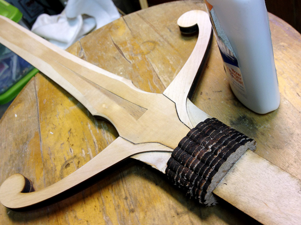
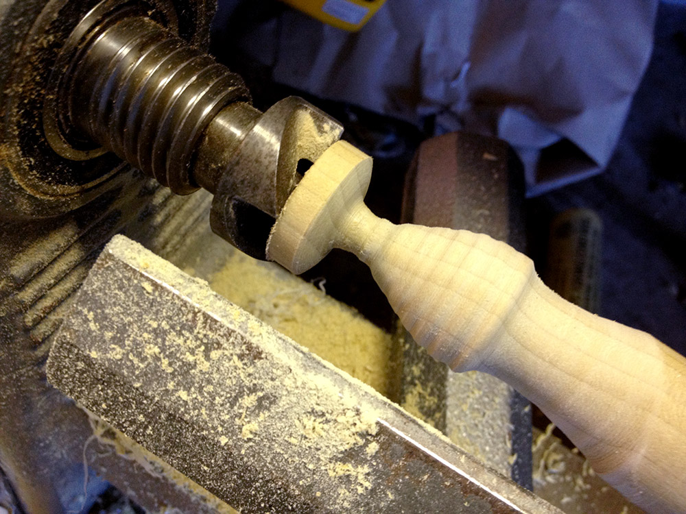
I ended up wrapping it with electrical tape to help protect the wood, and sticking it all the way though the headstock.  The wood is pretty soft, but I didn’t have to tighten the chuck down super tight since I’d be drilling it at high speed with a pretty slow feed.  I used some bits of blue foam to shim the wand so it wouldn’t wiggle.  When I drilled the finial, I used a collar to keep from drilling all the way though.wandThoughHeadstock

secretCompartmentDowl

With the secret compartments completed, it was time to think about finishing.   The kids were running around with the wands already, and I wanted a tough finish that could hold up to a lot of abuse but would look ok.   I decided to go with a polyurethane finish.   I use polyurethane a lot because it’s tough and dries quickly.  I usually use clear semigloss because that’s the most forgiving.   I’d never used colored polyurethanes, but I decided to give one a try for this project since I wanted a very distinct color and wanted to do it quickly.  I got a a very small can of deep red and started brushing.

The next morning I went out to the garage to see how it looked, and I was shocked to see that the finish had formed a really dark band on the side of the wand that was down while it was drying.   I can’t say I like the colored finishes because they really highlight unevenness like that.  Luckily I was going to build up quite a bit of the stuff, so I just kept changing which bit was the underside each time I let a coat dry. It mostly evened out.  No fun though.

simonWandFauxFinishI used red finish on the handle and clear on the body of the wand.    I wanted to make the wand look old.  I thought I could do that by just dabbing some black acrylic paint on, but since I’d never done that before, it was a little bit intimidating.   What if it looked awful?  I took a deep breath grabbed a paper towel and started dabbing.   I had to work fast because that stuff dries quick.   I dabbed and dabbed and eventually got it to something I was happy with.

It really highlights some of my not-so-perfectly-sanded areas on the finial, but I guess making it look old and dinged was the goal.   I’m pretty happy with the results.  Simon wanted the wand to be all black, which I could have done but seemed kind of boring.  He’s going to be upset if I make his brother’s all black.  I’ll have to come up with some other finish for that one, or Simon will be snagging it faster than you can say “Expelliarmus!”

secretCompartment2