Our cat likes to go out at night and his comings and goings cause us to lose a little sleep opening the door for him. He has never put up with a collar, so I got an automated cat door that can read his imbedded ID chip so only he can get in. I read in the Amazon reviews that the chip reader worked well, but that raccoons could learn to open it from the outside. We live in the boonies with lots of raccoons and other critters, so I knew that was going to be an issue.
 The problem seemed to be that the chip reader could dynamically keep the door from being pushed “in”, but cats were free to push the door “out” from the inside. Only a magnet keeps the door from going out. The door is shaped to make it hard to pull it out from the outside, but apparently raccoons can manage it. So I thought “I’ll add a beam break sensor and some extra locking so the door can’t push out unless my cat’s head is breaking the beam.”
A system like that would require an Infrared emitter detector pair and some electronics. I started designing it, and the design consisted of two timer chips, a bunch of resistors/capacitors some transistors, diodes, etc. I wanted it to fit into a pretty small space since I would have to integrate it into the existing cat door enclosure. For a long time I’ve wanted an excuse to try out some of those super tiny programmable CPU’s. They come with internal clocks so you can get away with very few external components, and you can tune the behavior in software. This cat door seemed like the perfect opportunity to give them a try. Time to lose some sleep in the short term to try to gain some sleep in the long run.
 I decided on the ATTiny85 because it has 8k of program space, features a wide selection of internal timers/interrupts/analog to digital converters, and cost only about $.85 each. They’re the kid brothers of the chips used for Arduinos. They use the C programming language and have GCC as the compiler. This sounded like very familiar turf. I ordered 25 of the little guys to get the lower price point, make sure I had plenty of extras, and avoid the embarrassing situation of paying more for shipping than for the parts themselves.

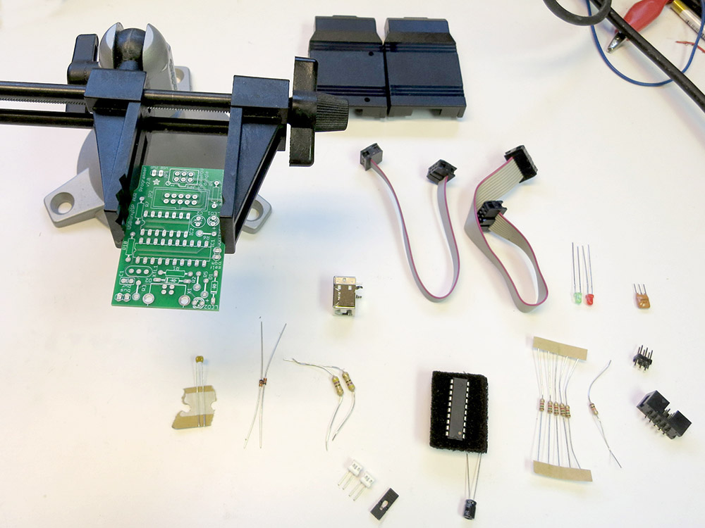
 I also ordered a USBTinyISP In Circuit Programmer that you get in kit form. This past weekend the parts came, and I soldered up the programmer. It’s all through-hole components and was pretty easy to put together. They have a detailed step by step build of it documented on-line, although I personally prefer just a parts list and a population diagram. There’s less scrolling around, and if you don’t happen to have a computer near your soldering area, having a giant scrolling assembly document is unwieldy.
 I also soldered up a board that has a Zero Insertion Force(ZIF) socket that wires the programmer to the program pins on the ATTiny85s.
I then downloaded the USB device driver for the USBTinyISP and the WinAvr tools, which include the compiler and a tool called avrdude that can use the ISP to program the chips. By the end of that day, I managed to get avrdude to talk one of my tiny chips. So far so good.
 Here’s a schematic of what I wired up to be able to program the chip. The 6 pins of the programmer header are shown from above.
It wasn’t until the next weekend that I got a chance to try to run some code on the chip. For the cat door project I need a 38khz signal to drive the Infrared LED. That is because the IR receiver filters out all non 38khz signals so it can reject ambient light level changes and all kinds of other noise in the signal. This is how pretty much all IR remote controls work and that’s why you can get a fancy receiver that does all the filtering for cheap. Be careful when choosing a receiver module. Since they are used for IR data transfer, many of them can’t handle continuous 38khz signals. If you just go get the receiver at Radio Shack, you’ll have to use bursts of 38khz to keep the receiver paying attention. That’s code complexity I’d like to avoid.
The ATTiny85 has timers/counters that can be set up to drive an output pin directly so I can setup the LED and forget about it. That’s much nicer than trying to toggle the pin myself with a bunch of interrupts or code loops. I found a nice overview of ATTiny timer programming and read though that. I then read the ATTiny85’s datasheet to figure out exactly how to set it up on my chip. With a full understanding of the chip, I should be able to avoid an unintended Rise of the Machines. I did, however, only skim some parts of the datasheet ,so if you get word that I’ve been mauled by raccoons, head for the hills.

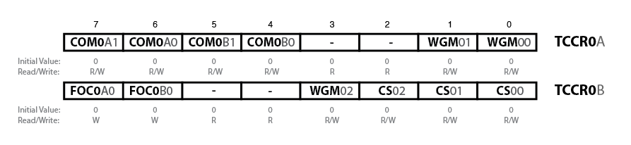
Sorry this is so small
To set up the timer, there’s really only 3 bytes you have to fiddle with: two Timer/Counter Control Registers and the Output Compare Register ,which is the 8-bit number the counter compares against. To have the counter run in a retriggering loop and have it toggle the output pin A each time it matches, I only really need to set these bits, and only two of those are non zero.
COM0A1 COM0A0
  0      1        Toggle output pin A on Compare Match
WGM02 WGM01 WGM00
  0     1     0   Clear Timer on Compare Match
My first attempt at programming the timers worked, but there were a number of problems:
- outputting on the wrong pin
- totally at the wrong frequency
The funny part was that my programmer was upstairs in the house, and the protoboard/power supply/test equipment was in the garage. I had to program the chip, pull it out and hoof it out to the garage. I went back and forth about 10 times. Who says hacking doesn’t provide exercise?
 I managed to get the output going to the correct pin. Then I got the clock prescaler turned off so the counter was getting the proper 1 Mhz clock. Finally I tuned the output frequency in to as close to 38khz as I could get. The counter counts up to a given number and then resets and toggles the output pin. I’d originally calculated the count should be 26 since 1Mhz/38Khz is about 26. Then I realized that the output pin toggles each time the counter is reset, which means the output frequency is actually half of what I was expecting. So 13 was what I was looking for. In the end I used 12, since the 1Mhz clock is only approximate (the chips running without a crystal) and it ended up being a better frequency match. Or it could be that you want n-1 since we’re counting from 0.
What do I think of the 8pin CPU’s VS a pile of timers and discrete parts?
I won’t really know until I finish this project. At the very beginning, this way has me spending more time installing device drivers, downloading and installing software, and fiddling with makefiles, etc. The other way lets you get right to the protoboard but is less flexible in terms of fine tuning the results. Now that I have the tool chain up and running, the rate of progress has really increased, and the the rest of this project should be less annoying. Tuning the output frequency might not have been as fast as adjusting a trim pot, but so far the only component I have is the chip! I really should move the programmer closer to my test bench.
I’m starting to get the sneaking suspicion that I should have just sprung for the AVR programmer that Atmel makes. It works natively with AVRStudio, which is the free IDE that they produce for their chips. You can get the USBTinyISP to work with it too, but it sounds like you have to go though some wacky contortions to do it. I think the only real advantage the USBTinyISP has over the native one is that it can also power the external board via USB. It also has a 10-pin programming header, but since I’m not trying to work with some board that has a 10-pin header, it isn’t much of an advantage.
I think if I were doing complex development with actual debugging, I’d go with the Atmel programmer just because it works natively with AVR Studio. As it is I’m just doing code dumps without any interactive debugging, so it’s basically: use your favorite code editor, write the code, and type “make”. There’s even a make target that downloads the code to the chip, so you end up typing “make program ” a bunch. Firing up AVRStudio for that would be way overkill. So for this kind of dev a USBTinyISP is nice since I don’t need an external power supply for my programming board. This WinAVR way is simple, pretty much worked right out of the box, and it’s much smaller and less bloated than an AVRStudio install.
Here’s the code so far. It just defines what pins I think I’m going to use, sets direction of the various pins, and configures the timer to toggle out of pin 5 of the chip. In my next installment, I’ll try hooking up the IR receiver I’ll also start dissecting the cat door, come up with a plan for how I’m going to lock it, and figure out what sorts of feedback and control I’m going to need. Hopefully I’ll get to play with using the external interrupts and maybe I can even try out some power-saving modes. I’d really like to put these chips though their paces and get a feel for many of the chips features. Clearly with 25 of these little guys, they’re going to be showing up in lots of projects.
#include <avr/io.h>
#include <avr/interrupt.h>

#define IR_LED_OUT_PIN    (1 << PB0)
#define MOTOR_OUT_PIN     (1 << PB1)
#define SWITCH_IN_PIN     (1 << PB2)
#define IR_RECIVER_IN_PIN (1 << PB3)
#define OUTER_DOOR_IN_PIN (1 << PB4)

int main (void) {
    // Make it so the input from the switch will use the internal
    // pull up resistor.  Other inputs will have no pullup, and the
    // outputs will all be low.
    PORTB = SWITCH_IN_PIN;

    // Configure the motor and IR leds as outputs, and all the
    // other pins as inputs.
    DDRB = RELAY_OUT_PIN | IR_LED_OUT_PIN;

    // Configure the timer 0 to output on 0C0A with no pre-scaler
    // and so it'll  CTC (count down and auto reset) toggle every time
    // it gets to the compare.
    TCCR0A = (1 << COM0A0) | (1 << WGM01);
    TCCR0B = (1 << CS00);

    OCR0A = 12;  // 1Mhz/38khx = 26.3  Then you have to divide by 2
                 // you have to toggle twice to make the full wave.
                 // so that's about 13.  With my clock 12 ended up
                 // being closer.  No prescaler needed for these high freq.

   for (;;) {
   }
}

 Grandpa Stan bought this 1962 Triumph Spitfire and has been restoring it. It had two brackets that hold the stabilizer bars, but his were horribly bent and broken. I guess those brackets are hard to get because he asked me if I could make some replacements.
 He gave me the the less destroyed of the two plates. I was able to get some rough measurements. I had sheet of metal with the same thickness, so the first thing I tried was cutting a piece out with the bandsaw and bending it into shape cold.
 Here’s the plate on the vice, and you can see the metal bar in the background. I put the vice on the anvil so it would be able to take some pounding. The plan was to heat the plate in the furnace, fish it out with tongs, and position it on the vice. My wife would then place the rod into position, and I’d hammer it down. We practiced it cold, and then gave it a try. We were a bit slow, so I ended up having to do 2 heats to form the channel, and then another heat to fine tune the transition back to flat.
 We banged channels into two of the plates, and it was time to put all this stuff away. At least we put on an interesting show for the kiddos. It was kind of a big production for two little curves.
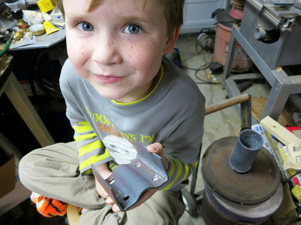
 We talked about drill press safety, like how it’s good to clamp the work down. We also discussed how to position the piece so if the bit catches, the part spins into something solid that is not the operator. He did a good job helping. I like his safety gear.
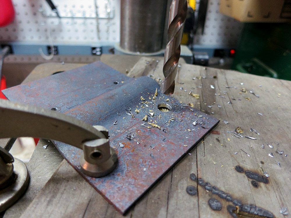 Once we had all eight holes drilled, it was time to bend up the wings at the edges. I just did that cold in the vice. One tricky part was that in order to not squash the center channel area, I had to extend the jaws of the vice a bit with some square stock.


 I ended up wrapping it with electrical tape to help protect the wood, and sticking it all the way though the headstock. The wood is pretty soft, but I didn’t have to tighten the chuck down super tight since I’d be drilling it at high speed with a pretty slow feed. I used some bits of blue foam to shim the wand so it wouldn’t wiggle. When I drilled the finial, I used a collar to keep from drilling all the way though.