When I first started restoring my Isetta, I swore off any non-Isetta related projects. I knew that project was so huge, and had so many different parts to it that it could act as its own heap of projects, and if I was ever going to get the whole thing done, I was going to have to focus.
Somewhere just before the end of the second year of working on the car, my project composure cracked. I wanted to do a big project. I wanted specifically to do something unrelated to the Isetta. I wanted to bust out. I did NOT want to be derusting or restoring something. I wanted to make something new. Preferably something a bit electronics heavy, something fun. Thus was born the Electric Scooter project.
Now let me just state that I knew I was biting off a fairly large project when I started this. The electric bike project was going to pale by comparison. First, with an electric bike you’re starting with a complete vehicle. You have wheels, a frame, steering, brakes, a place for cargo, in short, a whole host of things that are already there, and all you have to do is not screw them up as you add motors, batteries, etc.
Secondly when starting off on the electric bike, I had specifically decided: no drive electronics. Just a two-speed relay system that could be wired up in a few hours. Doing a high current motor driver is a big deal. There are a lot of tricky issues that come up that complicate the design. In short, I have studiously avoided projects that require chopping more then a few amps through a motor. The whole point of the electric scooter project was to face some of these tricky electronics issues (and have some fun doing it of course).
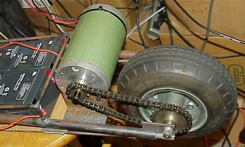
I drew some sketches and decided on an approximate size. Then it was off to the surplus stores to find a suitable motor. The motor would dictate most of the rest of the design. I spent a day digging through various piles of grubby motors looking for a DC motor with enough torque. I finally settled on a 50v motor which had started life as the spindle motor for one of those ancient reel-to-reel tape drives for computers in the 60’s. I also picked up two wheels, some sprockets, and some matching bits of chain. I decided I could run the motor at 48v from 4 12v lead acid batteries.
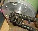
 It seemed like the first order of business was to determine what kind of reduction ratio to run on the motor to give me some decent torque, but also have a reasonable top speed. I bent a piece of black pipe into a ‘U’ shape much like the slide of a trombone. (Well a rusty thick-walled trombone slide.) I machined an axle, welded on some fitting so the axle could bolt across the two legs of the ‘U,’ and welded on a piece of angle iron so I could bolt on the motor. Now my trombone slide had a motorized wheel at one end. Still this was a long way from being a scooter, but I was itching to see what kind of power this thing was putting out. What to do?
Motorized Hand-truck Terrorizes Neighborhood
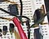
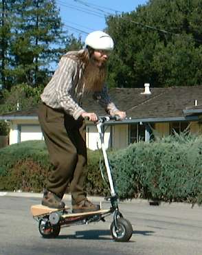
 Then it struck me. I didn’t need steering or brakes or much of anything to give this puppy a road test. All I really needed was a few more wheels. So I bolted the trombone piece to the back of my hand truck, put a board on top to sit on and to hold the batteries. I stuck the whole contraption into the street and climbed on. I touched two alligator clips together, and zoom! I was shooting up the street. Now let me tell you, I have done a lot of wacky projects on this street. The electric bike never even got a second glance. The completed electric scooter didn’t cause a stir, but by gum a motorized hand truck really brings people out. Within moments I was surrounded by neighbors asking what the heck that was. I guess my other projects just end up looking like something I might have bought, but throw together a vehicle with clamps, a hand truck, and loads of loose wires, batteries, etc, and everyone’s impressed. Go figure.
 It was clear that the motor had zip, and I guess I lucked out on my guess about the gearing because it seemed to be just about right. So it was back to the shop to build the host of things needed to turn a trombone slide into an actual electric scooter. I welded the rest of the structure using 1/4 iron rod to form box sections. It was strong, but wasn’t about to win any awards for being light weight. Still it looked nice and was easy enough to do. The next big issue was the front wheel. It needed to be articulated so I could steer, and my design also called for another pivot so the whole scooter could be folded up. What to do?
The Great Bicycle Caper
Now let me tell you I hate bicycle thieves. When I was in high school someone stole my red Schwinn World Sport right off our porch. It had been my first full-sized bike, had had many component upgrades, and had been my faithful touring bike on numerous bike tours. I had gone thousands of miles on that bike, and I knew every scratch and ding. When it was stolen, I wandered around town in a fog hoping against hope that I might find it parked somewhere. I knew that the thief didn’t appreciate that bike. Not the way I did. So you can understand why it took me some time to warm to the idea of The Great Bicycle Caper!
Now one thing I haven’t mentioned yet in the project is that I was not taking this on alone. My friend and former co-worker Pioneer was also on the case. He was there from the very first sketches on napkins over lunch. Now maybe Pioneer wasn’t doing the welding, or surplussing, or electronics design, but it was his enthusiasm for the project that really saw it through to the end. He was an excellent sounding board and made sure we maintained the appropriate goofy perspective on the project. He was also the person who talked me into The Great Bicycle Caper.
We had been looking for a cheap donor bike at various Salvation Armies, Goodwills, etc. with no real luck. For some reason those stores were either out of bikes, or wanted so much for them that it didn’t make sense since all I was really interested in was the front fork. Now I knew that one would show up at a garage sale at some point, but we were looking for a bike, and the sooner we found one the better. Pioneer had noticed a bicycle frame locked to a tree near his apartment. He pointed out that the wheels and components had been stripped, and that the frame itself was bent, but the front fork was still OK. I balked at the idea of stealing even this abandoned wreck, but Pioneer kept after me, working the angle that we would actually be doing a public service by removing this abandoned hulk. After a while he managed to bring me around, and I began to plot how best to steal this bike.
 The facts: The bike was U-locked to the tree. The tree was at a very busy corner right next to the entrance to a Cost Plus. The plan: I knew my angle grinder would make short work of the U-lock, but with an obvious shower of sparks, and we’d need electrical power. I also knew there was no way we were going to be able to do that unobserved, so going with the “public service” theme I outfitted us with face shields and orange safety vests. We put out some safety cones, and Pioneer ran an extension cord into the Cost Plus. We acted very businesslike. My grinder cut through the U lock in a mater of seconds. We rolled up our extension cord and ambled off with the bike frame.
This would have all been much easier if we’d had some sort of vehicle, but since I only had a motorcycle, we weren’t going to look too official showing up on that. Also riding a motorcycle while holding a bike frame would have been unsafe. So we had walked over from Pioneer’s place, and we walked back with frame in tow. I still feel a bit funny about the whole thing, but I do really think we were performing a public service, and that no one was victimized, so I guess I should just stop worrying about it.
The scooter takes shape
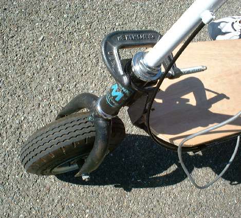
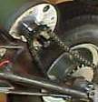
 I used a large lever arm to adjust the set of the bike fork, cut the fork much shorter, collapsed the ends, and cut slots in the flat areas to create a place for the front wheel’s axle to bolt. I mounted the fork, extended the handlebar’s stem to be much longer, and suddenly the project started to look like a scooter. As a quick initial test I cut a piece of plywood to act as a deck,
stuck some batteries in, and wired a switch to the handlebars. No brakes, no speed control, but it was time for a test run. I climbed aboard and I was off. After a little bit of use the power switch welded itself shut, and I found myself abord a runaway scooter with no brakes!
I leapt off and hauled the scooter into the air to keep it from running away. It was heavy, and the rear wheel kept brushing the ground. Now the question was how to disarm this howling squirming scooter. I clawed as some wires and eventually managed to disable it. Now we were having fun! After that all tests were carried out with an exposed loop of wire which could easily be yanked free. A kind of “nearly dead man’s switch.” The next order of business was to try a relay controller. I wired up a big relay and hooked that to a control switch. Pioneer and I tried this configuration out with a bit more trepidation, but things seemed to be going well.
Eerie Lights shine under the scooter
However, we did notice two things. One was that when you released the switch, the motor did not cut out immediately, and two as darkness fell, we noticed the occasional eerie glow coming from under the scooter. Was the scooter possessed? Was it space aliens? Nope. It was the glow of an electrical arc shining out from the relay. Because the motor was running on high current DC power when the relay opened, it was striking an arc, and electricity was still flowing through the relay even after it was fully open. Needless to say the relay did not last super long under these conditions. Scratch one relay. I’ve often wondered if there is a simple passive capacitor circuit that would keep the arc from starting until the air gap was wide enough. Who knows? It was back to the motor control drawing boards.
Boring Technical Stuff About the Motor Controller
 Now I had sworn off high current chopper-based electronics projects for the same reason I don’t do high frequency digital electronics. To many spooky issues involving high speed transients taking advantage of parasitic inductances and capacitances. The circuit designs can get pretty finicky, and you end up putting a lot of ground planes around and just hoping for the best. Also when you are doing high-current stuff, you end up having to deal with more expensive components, heat sinking, thermal runaway, great big gate capacitances, larger explosions, etc. In short it’s a much bigger pain. There are some very nice websites about these issues. The Q4D folks have a very helpful site that talks about some of this, and SGS Thompson has a number of very interesting (well for motor control geeks) technical papers relating to this.
 I spent two months making various prototypes of my motor controller before building one that wouldn’t blow up when I actually tried it under full load on the scooter in the street. (That’s two months when I didn’t have a day job, so that was a LOT of time.) However the design I have in there now is pretty much exactly the design I started out with before I had decided I’d try and make all but the power MOSFETs be components that you could get at Radio Shack. What a mistake. I was building push pull stages to play tug of war with the MOSFET gates, and those stages always ended up having crazy noise issues, or suffering from thermal runaway, and just popping right off the board. So I finally caved in and bought a SGS Thompson gate driver chip. It pretty much worked right out of the gate. I didn’t even blow one of them up, and I think they cost less than $2, so it was dumb not to be using them from the outset. Still I learned a lot.
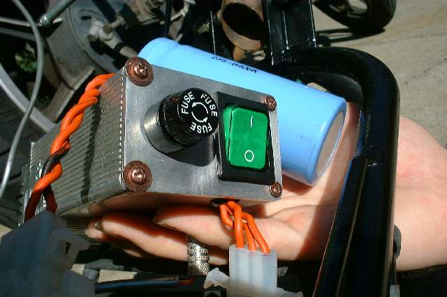
 I etched a number of different designs, but somehow even though they worked on the bench on protoboards under pretty heavy load (sticking a 2×4 against the rear wheel), they’d still blow up once I had them etched and was testing them under full load. Finally I managed to build one that didn’t blow up. It has some issues where when it goes to 100% on it has a lot more power then at less then 100% so it feels as if you have variable slow speed control, and then a kick of extra power when you go full throttle. Which is fine although I’d like to know what is really causing this. I boxed the whole thing up in an aluminum box with a big heat sink sticking out one end. The nice thing is that it’s all in one module, so I could pull the controller out and stick it into another project if need be.
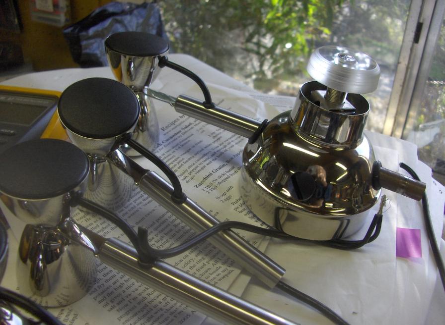
Making The Throttle Handle
 After the motor controller was working, I needed to make a nice interface for controlling the variable resistor that was the throttle. I decided a “motorcycle” style twisting hand grip would be swank. So I cut off part of one of the handle bars just inside the hand grip. This part was to be the twistable throttle. I measured the amount of twist needed to go from idle to full on my motorcycle, and I made that be the amount of twist available on the hand grip. Now Mark has been dabbling in clock restoration, and he was a great source for some spring steel that I used to act as the return spring for the handle. Finally I used a toothed belt to hook the twisting grip to the potentiometer. All in all it makes a nice motorcycle hand grip, but it was a fair amount of work to make. If I were to do it again I might opt for a snowmobile style thumb lever or some such at least as a first pass.
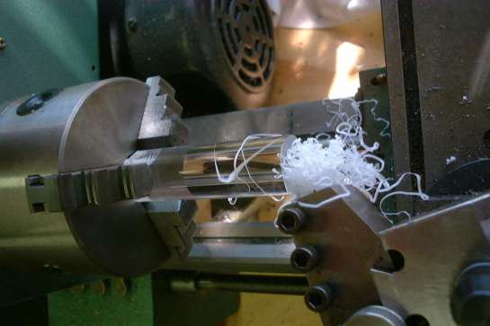
So It Goes. What About Stopping
 The next thing to consider was a brake. You would think I’d have made one of these earlier, but where’s the fun in that? I got a surplus stainless steel disk, and mounted that on the rear wheel. I had been planning to use the spent brake-shoes from my motorcycle in a custom caliper made from some chunks of AL plate, but there were space issues, and it seemed like a complicated build. So I eventually opted for an off-the-shelf caliper that I got at a go-cart shop. It was fairly small, and was already fitted for cable drive. So that made things a lot simpler. I brazed various cable connections on the scooter just like a real bike, and ran the cable up to a brake lever on the handle bars. Suddenly trying out the scooter was much less scary and entered the realm of something casual guests could try.
Dressing It Up
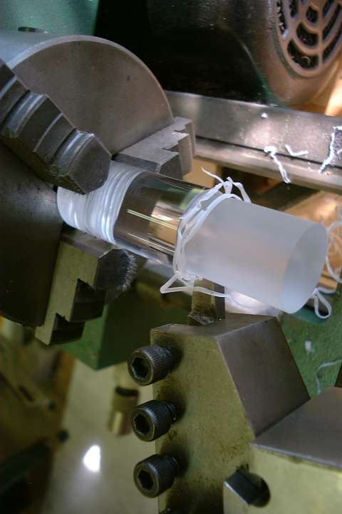
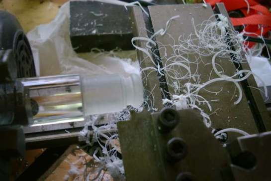
 So then there were the countless cosmetic improvements. I made a center stand for the scooter. I made a clear plastic deck for the scooter with a nicely patterned grip tape surface (thanks to the local skate shop). That and a nice paint job, and it was looking pretty good. The scooter still sports a fairly silly plywood “kick tail” that I added for ergonomic reasons. It turned out that otherwise the foot you had at the back would be at a somewhat uncomfortable angle. Also I still have never made a build-in locking mechanism for the folding action of the scooter. I’ve always just used a C clamp.
Speed, Range, and Showing It Off
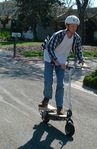
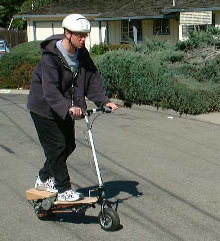
 Well at this point, it was pretty much ready for folks to ride. On several occasions my friends came over to check it out and ride it around. Top Speed? Well I’m not entirely sure; my best guess is something like 12mph. Weight? The bathroom scale claims it’s a chunky 56 lbs. When I built it
weight was not the highest priority. I’m sure it could shed quite a few pounds with a cast AL frame and lighter handlebar stem and tires. As it stands, it’s quite rugged, but no featherweight. Most of the weight comes from the 4 lead acid batteries and the motor. Not much I could do about those without a full redesign. So now comes the question of range. How much range did it have? Everyone wants to know about the range. Honestly I just don’t have a clue. In all the times it’s been ridden we either didn’t ride it enough to run down the charge, or it wasn’t fully charged to begin with. So I guess the answer is that it had enough range to out last our attention span for riding it up and down the street or around the block. It just isn’t really comfortable enough to want to take it for range trials around and around and around the block.


 The other day my son Pioneer brought home a paper lantern from preschool. Around that time we also got some pastries in an interesting paper to-go box that had four sides and folded up into a nice curved shape. That got me thinking that I hadn’t done any paper projects in a very long time.
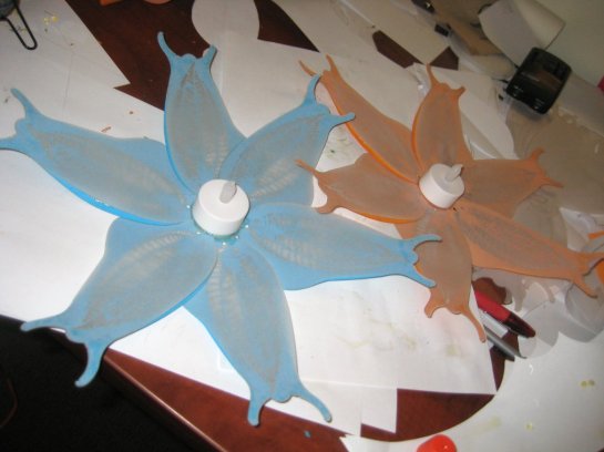
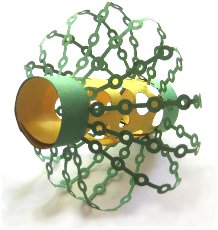 I initially thought I’d make a lantern a bit like the one Pioneer had made, but with much more detailed cut outs. I produced a few little prototypes out of construction paper. I didn’t get a picture of the better lighting bolt themed one, but I did take a picture of this green and yellow one, but wasn’t satisfied with the way they looked kind of spindly. So I thought maybe I’d make a more enclosed lantern a bit like the to-go box I’d seen, but with nice patterns formed by using two layers of paper with the pattern only cut into one of them. I experimented with various patterns, and also started looking for the right overall shape. With paper, scissors and tape I made a number of 4 sided prototypes, and then a 6 sided one. That seemed more pleasing, and I second 6 sided one that I eventually went with.
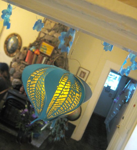
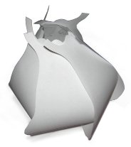 I knew I didn’t want to deal with actual candles, and thought LED candles would be excellent replacements, without the risk of fire and design constraints that would impose. I found Pier 1 Imports selling 4 small LED Candles for $5, so that’s what I went with. When folding up the various paper lantern shapes I realized it was important to do that with a light inside the paper so you could see the patterns that the paper overlaps where forming. I eventually made a prototype where the overlaps formed a flower, but because I was later constrained to some fairly opaque paper for the colored layer of my lantern I didn’t take that prototype any further.
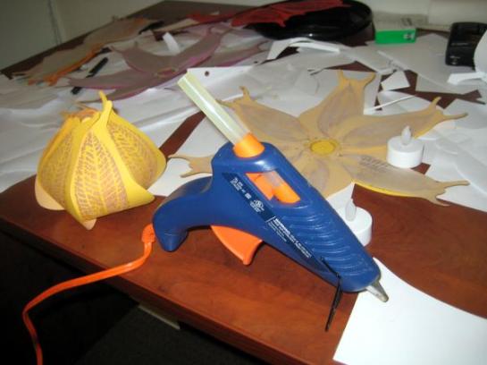
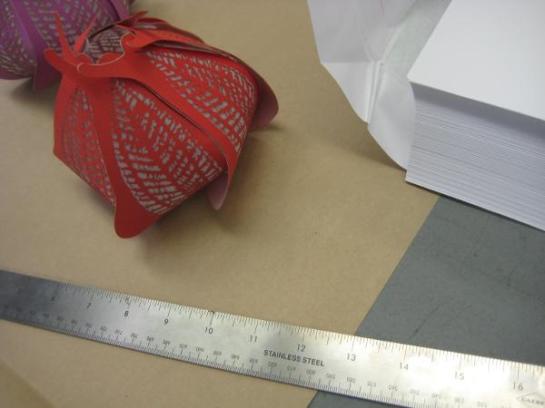
 Time was running out, so I did a quick pattern design based on a leaf, and thought I’d get cutting/gluing in no time. However I ran into a problem. The super detailed pattern took about 30 mins on the laser at it’s highest speed. (Enough pieces for two lamps) I thought I could avoid this bottle neck by stacking up a bunch of paper and cutting it all at the same time. However the massive amount of air flow in the laser chamber and the direct stream of compressed air at the cutting point made it so the paper would not all lay perfectly stacked up, they’d puff apart and chads would fly, and all this mayhem made it ineffective at cutting more then two sheets at a time. I ruined 3 extra sheets of paper on that first run because the lower sheets were somewhat cut, but not well enough cut that the chads would drop out. It was horribly time consuming to try and hand poke/trim out all these suck pieces, and so I decided I really could only cut two sheets at a time.
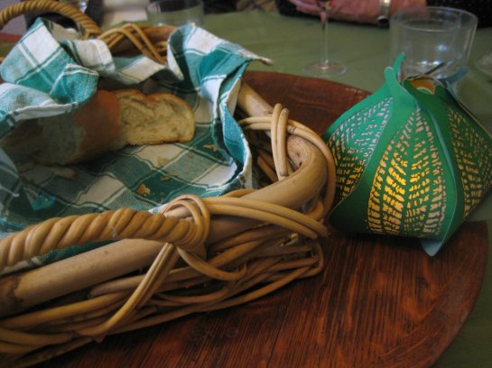
 Then I had to assemble things things. For each lantern there were 6 pieces. Three patterned colored outer pieces and three vellum inner pieces. I used a glue stick to attach the inner and outer pieces together in pairs (only gluing at the top/bottom). I did this because glue stick doesn’t cause the paper to wrinkle/warp the way Elmer’s glue does. Then when I had 3 pairs glued up, I’d glue the base rings of the 3 together with yellow Elmer’s wood glue. (for strength) I’d glue the LED Candle to the center of this stack with hot glue. (Quick, and with good gap filling.) Then after that had set up I did the final gluing of the upper sections. (again with Elmer’s) The final glue step was the most painstaking, but not too horrible.


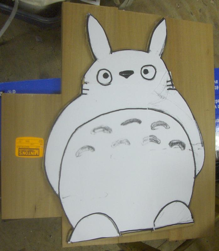
 I decided on an overall scale for the project, and I was off to the races.