This year I’m building an encryption device for my Retrotechnology Society. If you recall last year 6 of my friends/relatives were “antecedently” inducted into a secret society. The only down side being that the society was so secret that I never heard back from anyone. This year I’m going to change all that by providing them with this encryption device, so they can communicate with me (and one another) in cipher. Functionally it’s based on the 1850’s Wheatstone Cryptograph, design wise I’m working on spicing it up a bit.

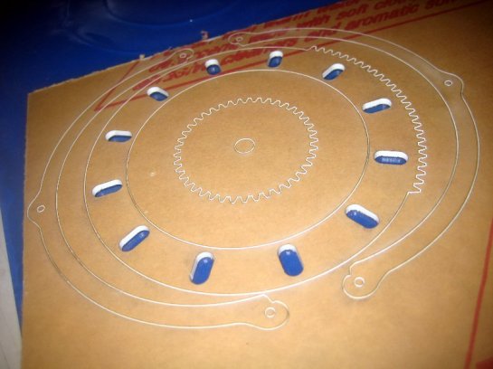
These images are of the very first prototype. It’s totally rough. I want the basic shape to be the Retrotechology Logo of the 11 toothed gear with an eye in the middle. I’m trying to design the eye so that it “looks around” as you encode/decode messages. You turn the thumbwheel at the upper right, and that drives two gears which turn two rings of letters which are visible though two openings in the face of the device. The eye design is really rough, and various spacings will be adjusted, but this is mostly just a proof of concept to make sure things are actually going to be functional.
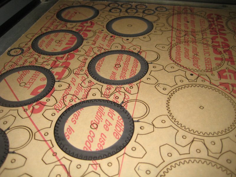
These were laser cut out of clear 1/8″ acrylic. Later versions will have to have clearance areas etched into various parts, etc. (to prevent binding) and I’ll have double brass sleeves acting as the bearings. (right now it’s all just jammed in 1/8″ brass rod to hold it together enough to make sure things were working out.) I like how it’s coming out, but I think the aesthetic of the eye design really has to be worked out some more. Still I think it’ll be fun. The final color scheme is going to be black, with white disks inside. I haven’t deiced yet what to do with the back. I could add some cutouts that would expose the gearing a bit. Kind of a skeleton Cryptograph, but that might make it less functional. “keep your fingers and crud out of those holes!” so I haven’t decided. Maybe just a redux of the eye.
I wrote the code to generate the gear profiles in python, and then imported that into illustrator and did all the rest of the work there.
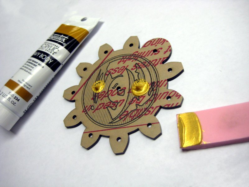
 Ok, so then it was time to cut out real versions in the right colored plastics, etc. I used black for the outer casing and “Ivory” for things like the friction wheel, and the lettered discs. In the design the black front/back called for gold and white lines. I thought this was going to be a real pain to do, but I came up with a trick. I used a little rubber squeegee (cut from a Speedball rubber pad) and was able to squeegee gold paint down into all the lines and curves in a jiffy.
 This squeegee system reduced the amount of paint used, and really speeds up the whole process. The fills are more uniform too. I don’t want the fills to be perfect because the device is supposed to look sort of old, but the amount of time I was saving painting all that stuff made using the squeegee super important.
 Once the splops were on, it was just a couple of strokes to fill every line.
 I did have to manually clean out the center hole. It doesn’t matter if there’s a bit of extra gold paint in there since it’s going to have a brass tube pressed in, but we can’t have a thick blob.
 If you look closely you’ll also see that I have scraped the outer ring free of most of the gold paint using a paper towel and my fingernail. Then I painted white over the top.
 These are the faux Ivory thumb wheels with their special strate knurl, and inlayed arrows. (Done with the same painting technique)
 I would have rather had the gears be “ivory” but since they’re not actually visible, I was able to cut them nested inside the other black components, and save a lot of material. I’ve toyed with the idea of making a fancier gear and a “skeleton” version of the Cryptograph, but decided to punt. The dark rings and little “tabs” you see in this are places where I’ve etched extra clearances on the gear/outer wall of the device so that friction wheels can run more smoothly without their knurl making their action feel “notchy.”
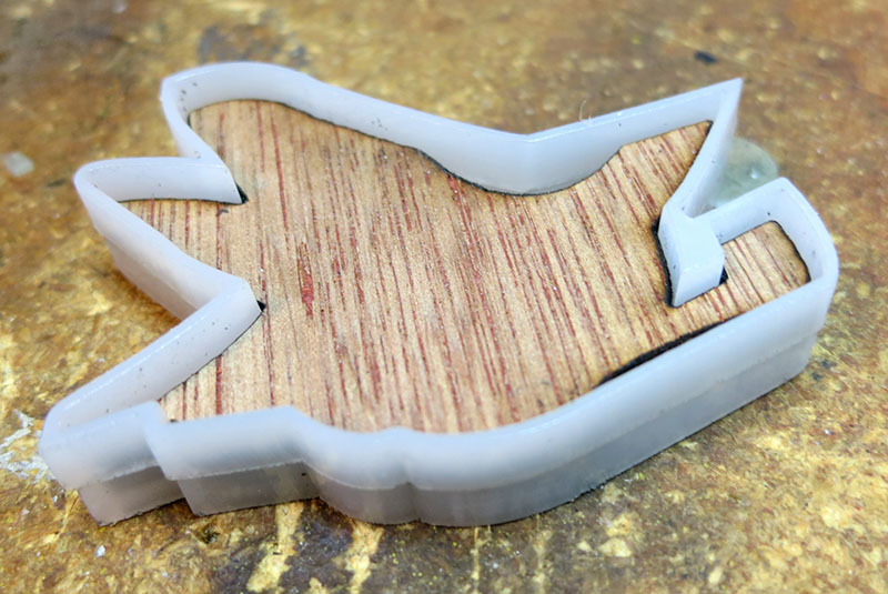
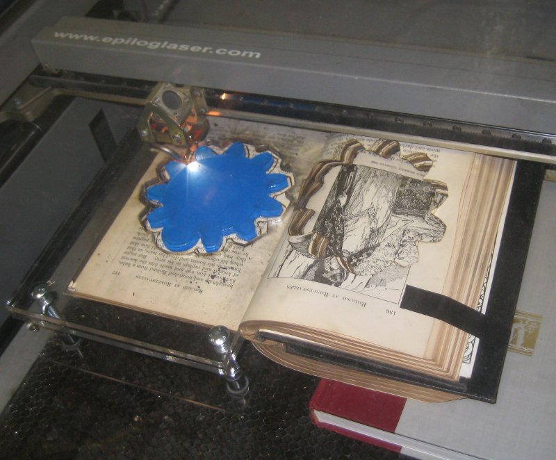
 I also did some initial tests of burning a deep deep hole in a book. I’ve had people tell me it’s impossible to laser cut books, but you can. You simply have to clamp the pages together so they aren’t as prone to catching fire. I laser cut a clamping jig, and the first cut went well. (Probably 1/4″ easy) but subsequent cuts are bad because the loose paper and forced air cause a lot of burning. (I remove the inner paper, but the walls aren’t as well clamped as they were before and there’s a lot of smoke and mayhem. So I think I’m going to have to change the way I index the rig and flip pages/reclamp after each cut until I get to the needed 5/8″ inch depth. Still here you can see a piece inside a book with only minimal effort. I don’t think I’m going to glue or do anything extra. Just cut the hole so the device can be tucked into the book for safe keeping.
I did this test on a volume of a Funk and Wagnalls New Encyclopedia. (Millions were given away free in super markets back in the day, and it’s hard cover with gold outer trim, so it seemed like a good call.) I really need to find some uniform nice looking old hardbound books that no one wants/cares for. Not sure how I’m going to do that, this thing was $4 at Goodwill. I have no idea why anyone but me would buy such a thing, and that’s a kind of steep price! If I could have snagged 10 volumes of this F&W I might do that, but I’ll have to keep looking.
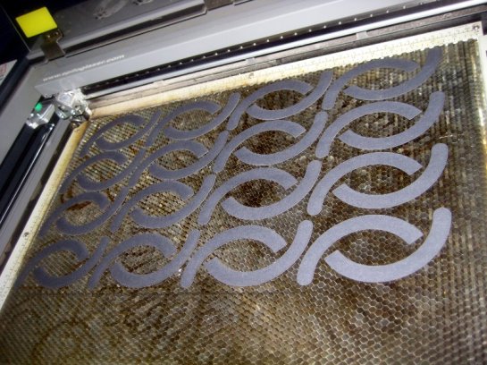
 So this morning I started assembling a final unit. Here’s the parts mostly laid out. They gray part of the eye is supposed to look a bit rough like that. I want the device to seem a bit old, not super crazy snappy new.
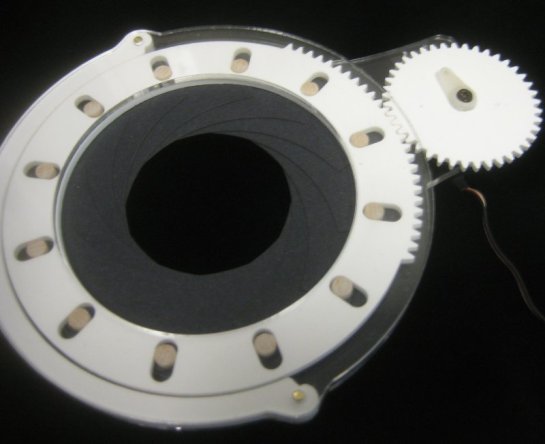
 Here’s the body assembled with its 11 pins in place. (11 pins! I have to cut and deburr all those by hand, 1/8″ is a bit small to automate on the lathe. (Kill me.) You can also see the super fancy inner pin that drives the middle disc via a square drive shaft that passes though the center of the other gear.
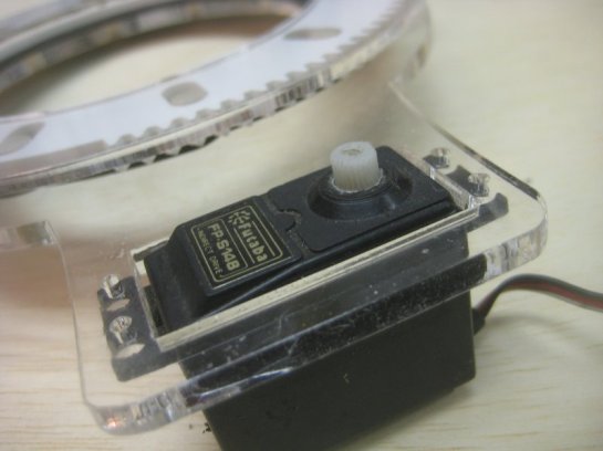
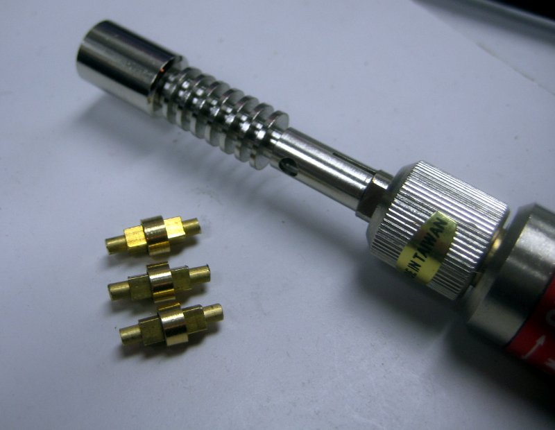
 Here’s a closeup of the friction wheel on it’s shaft. You can see it’s inner brass sleeve.
 Here you can see the most complicated brass part for the project. Most of the 18 brass pieces are just bits of rod or tube, but the central drive shaft is made up of a brass rod, and square brass tube, and then a custom machined brass tube (the needed to be machined so that it nested to the outside of the square tube and then nested properly inside the 1/4″ brass tube sleeve that is in the center of the upper gear. This shaft lets the bottom gear smoothly drive the lettered disk that is on top of the upper gear.
I was originally going to solder the bits together, but they pressed together so nicely all I really had to do was add a dab of JB Weld to eventually fix the central rod to the inside of the square shaft. This let me adjust things up/down slightly on assembly. Which was nice.
 Another device nearing completion.
 Here you can see four of the devices, three done, and one just needing to have the bottom paper pealed off. You can also see last years wax seal, and some sealing wax because I’m about to put the devices in their books and package them up for shipment.
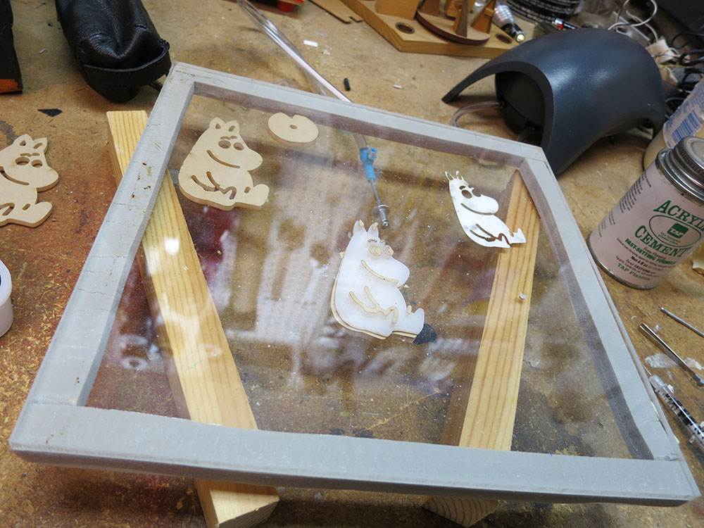
 The process of cutting the books was a real messy pain. In order to be able to cut a lot of pages at once I had to make this book press which clamps 80 some pages at a time, and lets me do alignment of the cut. You can see the little ‘L’ shaped page alignment guides for positioning the corners of the page.
 The problem with cutting so much paper is that you have to go slow, and the compressed air blowing in the machine makes the paper char a lot more then it would for cutting just a few sheets. So there’s a lot of char and mess, and although you only spend maybe 3 mins in the laser doing each cut the time it takes to do a cycle (take out the old paper, clamp up the new paper, and tape things up so various pages don’t fly around while the laser is cutting, etc. eats up a lot of time, and you have to watch the cut like a hawk to make sure it doesn’t go to open flame, or something comes untaped and is flapping around, etc. Nothing I’ve ever done on the laser before was “messy” in this way.
 In the end I did manage to cut 6 books before Christmas.
 I was lucky to get this 1909 lavishly illustrated 12 volume set of “Adventures in Bookland” which was great because they were all the same size, which simplified alignment. I got all of them (plus some more books) for $5 at the Friends of the Library book sale. So it was a great deal, but I paid a heavy price in terms of guilt. It was horribly Fahrenheit 451 and I felt awful cutting though all the stories I knew like Robinson Caruso, etc. I’ve kept all of the cut out illustrations for possible future use, but my hands have run black with the blood of many an old book and that made me feel bad.
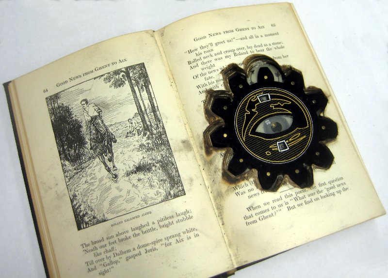
 Here is an image of the device in a book. I love the way it looks like the device has burned its way into the book.
 Here’s a close up of it in the book. The “top” page here is quite burnt because it was exposed to the most compressed air laser action. Intermediate pages were much less burned looking, but every sixty pages or so theres are a few really burnt ones because that was the next layer I cut. Alignment between the layers isn’t perfect, but it’s decent. You can see I added a faux window reflection that holds still as the eye looks around. I’m really proud of the way this turned out. Now to see if I get an encrypted messages!

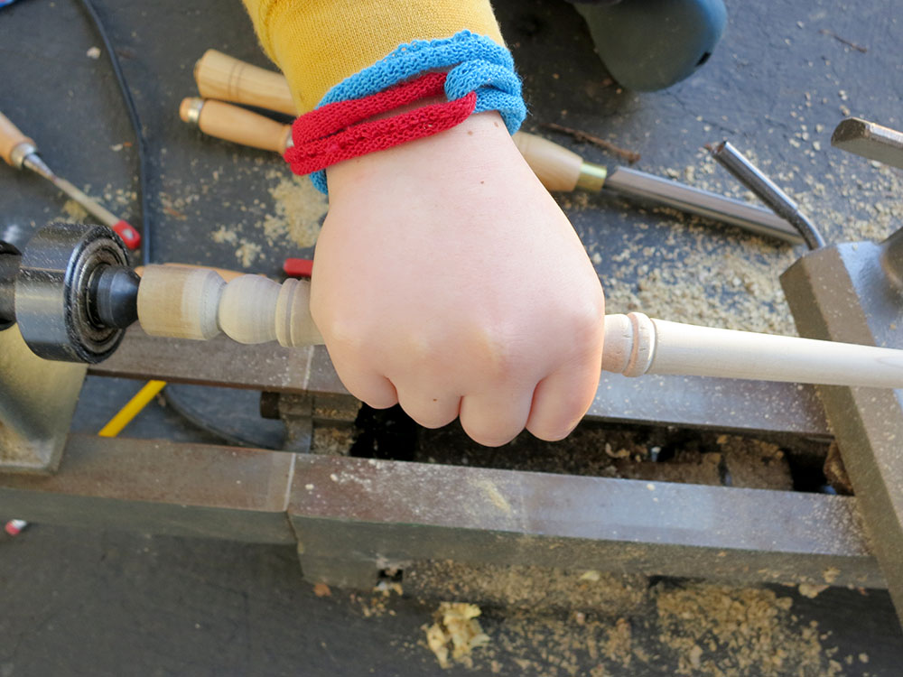
 In the run up to Christmas our family went to Dickens Faire, and my son really wanted to buy a wand at the wand shop. I told him we could make one at home. Now that the Christmas rush has passed we’ve finally gotten around to making one.