Making a Pop-Up Card

When I was growing up, I did a some bike touring with my dad. My uncle joined us on some of those trips, including one summer the three of us spent biking around the British Isles. We slept at youth hostels and biked around England, Ireland, and Scotland. Sometimes when I lagged behind, my uncle came circling back and said something like “Oh no! A honey dipper truck turned over in the road. I had to turn back.” to jokingly explain why he was coming back to ride with me and keep me company. I really appreciated that.

When I heard he was seriously ill, I booked a flight to go visit him. With my flight 4 days away,  I thought I would make something small to give him. I figured this might be the perfect chance to try my hand at making a pop-up card. I remembered one time in Scotland we zoomed down an hill and suddenly come across a lot of sheep in the road. None of us crashed, but there were several close calls. I guess a big dose of adrenaline helps make a lasting impression.

Making the card was going to be a race against the clock. If I could design and laser cut all the parts after work on Wednesday night (the night I have free to go to TechShop and use the laser cutter), I could spend some time Thursday night gluing the whole contraption together to have it ready to take on the plane with me Saturday morning.

Graph Paper Sketch
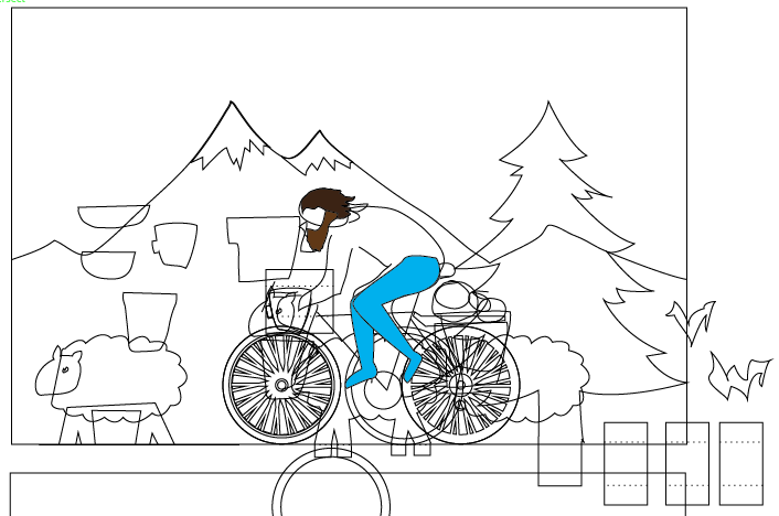
The first thing I did was a quick sketch of the idea in my notebook.  I put in a mountain, some foothills, a tree, my uncle on his bike, and a sheep.  I figured that would be enough layers to give the final project some depth without having to design too much stuff.  I also did a quick diagram of the various depths of the things and the road my uncle would be biking on.

I made a few notes about what colors of paper I’d need, and then I headed to  the store.  When I got there, the woman at the counter told me I had five minutes before they closed!  Oh no!  I rushed into the paper section and started grabbing sheets of colored card stock.  In my mad rush to get paper, I ended up buying nearly $20 in paper sheets.   It turned out to be a good thing that I didn’t spend too much time choosing paper because my laser reservation was at 10pm and still needed some design time before that.  I snagged a quick dinner at Clark’s and headed back to work.

Illustrator Bike Card Design

I went back to my desk and fired up Illustrator.  I started with the bike wheels.  I knew that with the laser I could cut all those impossibly delicate spokes without even breaking a sweat, something I’d never try to do with an razor knife.  I also designed the spacers and hinge flaps that would anchor the parts and allow them to fold.

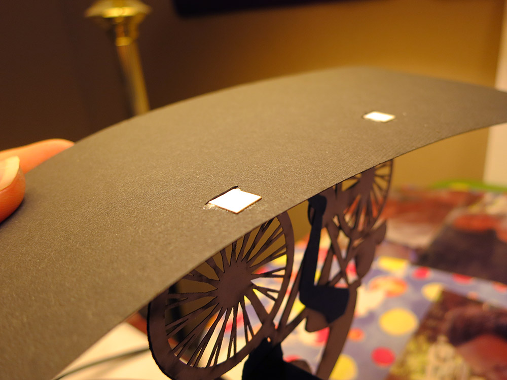
I used dotted lines to perforate the sheets where the paper needed to fold.  At 9:30pm, I headed over to TechShop so I’d be there for my laser reservation, but I took my laptop along since  I still wasn’t done with the design.  I knew I could cut single sheets of paper at the machine’s maximum speed, but I had to do some test cuts to determine what power and pulse rate to use.  I was able to get some settings that didn’t burn the edges of the paper much.  With a low enough pulse rate you can even get the paper to be sort of microperfed, but not fully cut, in in some spots.  This can be handy because the compressed air and blowers clearing the air in the laser can make your tiny pieces of paper get sucked into the exhaust system as soon as they are cut free.

Jumble Of PartsI spent the first hour of my reservation frantically finishing the design. The second hour I worked on the laser cutting, swapping sheets of paper into the machine to cut.  I finished just at the stroke of midnight. I took my pile of laser-cut paper parts home tucked into my notebook for safe keeping.

At this point, I needed to make some decisions about glue.  In the past, I’ve used 3M’s Super 77 spray glue for paper, which works well, but doesn’t give you much chance to position parts once they’re in contact.  So that was out.  I’d used decent quality glue sticks, but those were far too blunt an instrument for something like my super tiny bike tires.  Strike two.  I’ve used white glue for some fairly stiff card stock, and although it is very strong and has a decent working time, it causes wrinkling if you use it on a larger area.  I had to figure out something else.

Two Glues

I did some reading online, and the next day at lunch, I bought two kinds of glue:  Zip Dry and Tombo Mono Multi.  Both where supposed to work well with paper.  I ended up being glad I got both.

Zip Dry is like super-refined rubber cement.  It even smells like rubber cement.  It has enough working time to fine tune the part positions. And cleanup is super easy.  You can rub excess away cleanly and all you’re left is a pile of rubbery crumbs that can be brushed away.

The Bike Glued Together With Zip DryThe Mono Multi is white but supposedly dries clear. It gave me enough working time to position parts and set up fairly quickly with a strong bond.   The big down side is that it’s far worse in terms of cleanup. Excess glue has to be skimmed away immediately or you get an ugly, sticky patch which can not be cleaned away without damaging the paper. It doesn’t much matter that it’s “clear” at that point.

An overnight test of the two glues showed that Zip Dry is not as strong as Tombo Mono Multi.  When I peeled apart the pieces of paper I’d glued, the Zip Dry parted at the glue line while the Tombo Mono Multi delaminated the paper.

This turned out to be just the right combination of glues.  The Zip Dry worked for things like delicate tires on spoked wheels, and the Mono Multi held together the flaps and hinge pieces that needed extra strength.

Paper Roy On Bike
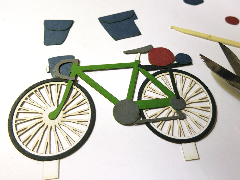
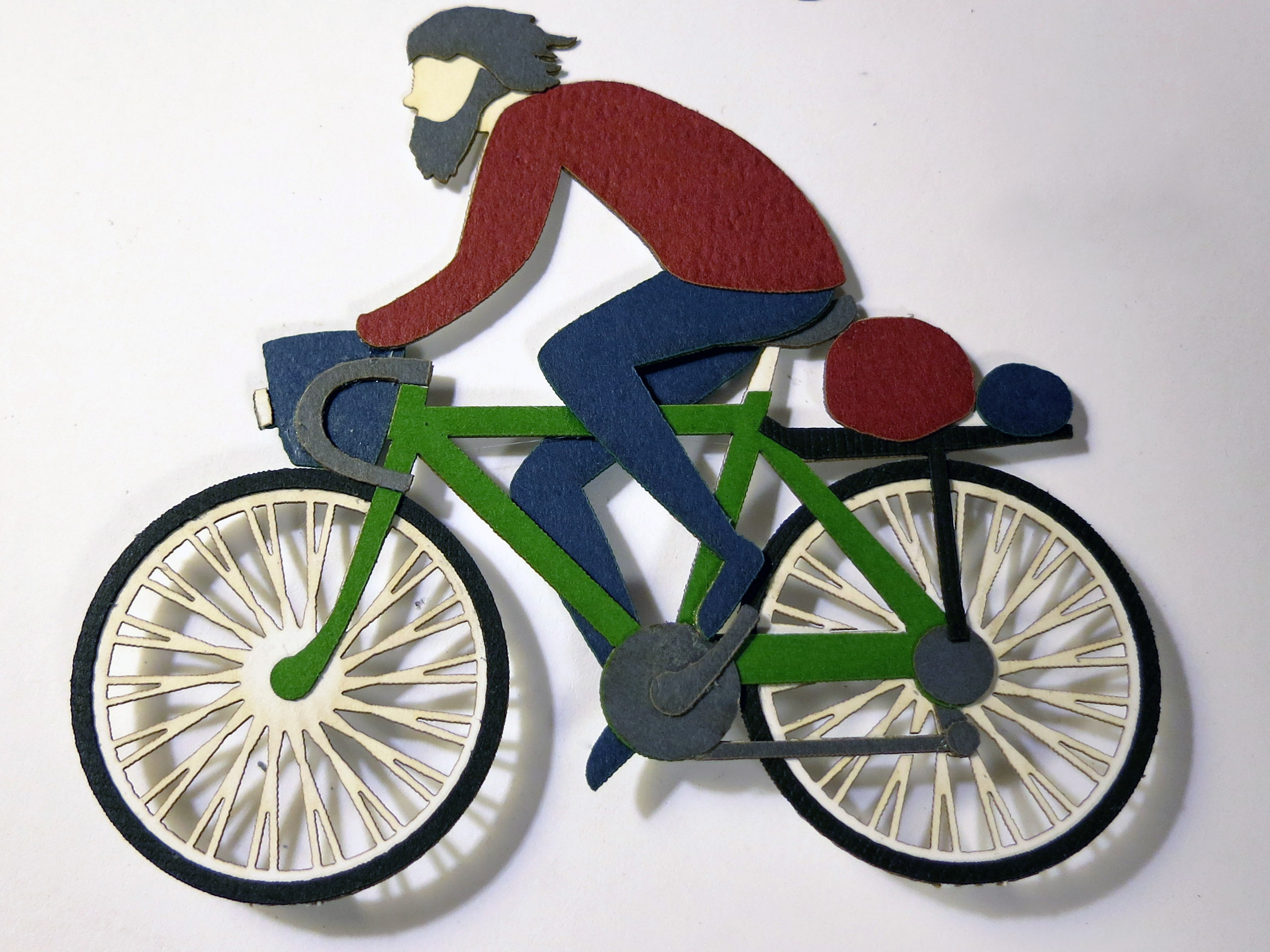
Here is my uncle on the bike fully assembled.   I also completed the sheep and glued up the tree and the mountains. It was time to start assembling the card proper.  My main concern when laying out the card was that the objects must be at least as far from the front edge as they are tall so nothing would poke out from inside the card when it was folded up.

I also wanted to add some struts behind each object, forming a parallelogram between back of the object and floor of the card.  This parallelogram is what lets the object fold down flat and pop up when the card is opened. I know real popups use other kinds of tricks to make things unfold, but I didn’t have time to do any research into it. Just the basics!

Bike Flaps Glued Under the RoadOne thing I did do right was to pass the bike’s white hinge tabs down through small slits I made in the road surface, and then gluing the tabs to the under side of the road.  The white tabs from the wheels would have stuck out like soar thumbs if they were visible. It made the bike look like it was really standing up on the road surface. I wish I’d also done that for the sheep’s feet, the tree trunk, where the struts glued to the foothills, etc.  That would have looked a lot nicer.

I started assembling the final card.  My layers were mountains, foothills, tree, bike, and sheep.  Each object had tabs at the bottom and struts that push/pull the object when the card opens and closes.  The object and the sky on back of the card  had to be parallel, and the struts had to be parallel with the road surface bottom of the card.

Hill With HingesI glued on the mountains, then the foot hills.  I discovered that the strut for the sheep was impractically long.  I thought it would bow when pushing, so I improvised a little vertical leg half-way along to help it stay even.

The exact positioning was somewhat improvised since I had had to rush the design and wasn’t able to spare much time for the actual mechanism.   If I’d had another 30 minutes, I could have laid out slits in the road/background that would have hidden the various glue tabs and made the positioning exact.  I would definitely do that next time.

The loosy goosey by-hand approach made me use a somewhat tricky system where I would glue the object down, glue the strut to the back of the object, and then put a dab of glue on the other end of the strut and fold the card shut.  This method forced the tab to be glued in the correct position and ensures that the card can close fully.

Glue ScrewupHowever, if I put too much glue and there was glue squeeze out, the card would glue itself shut.  Not good!  I carefully worked through gluing the mountains.  Fine.   The foot hills.  Great.   The sheep.   No problem.   Then I put the last two dabs of glue on the bike and the tree.  The card was almost finished!

Disaster!  On the very last action of making the card, I accidentally folded the struts up  instead of down when I was closing up the card. The two struts glued themselves to the sky!   NO!  The Tombo Mono Multi sets up fast, and I wasn’t able to detach the two sheets without tearing some ugly rents in the sky. Oops.

At that point, I was too exhausted to quickly design some clouds, birds, or UFO’s to cover the mistakes.  Thankfully, I still had some more of the blue- lined paper, and I was able to hand cut a patch.  The horizontal lines do a good job of hiding the fix, and for the most part no one can see it unless I point it out.  *Phew!*   The card was done.

I shot a quick video of the card opening and closing.  There’s also some footage of the bike being laser cut.

Sadly, my uncle died before I could give him the card.  I don’t regret making the card though.  It was nice to have spent that time thinking about him and our trips together, certainly much better than spending that time waiting and worrying.  I did give the card to his son.  Now I’m the only one who remembers that wonderful summer.  I wish I were a better keeper of the past.

popUpBikeCard

Using the Sun to Make Glass

pioneerMixing

Pioneer squirms on the hot driveway.

Have you ever wondered if you could use a magnifying glass to melt sand into glass?  I have a very large Fresnel lens that a coworker gave to me when I worked at SGI. Using it is kind of scary.  I keep it covered while I’m carrying it around so as not to accidentally set something on fire.  I’ve used it to burn wood, but I wasn’t quite sure if it could melt sand.  My son Pioneer had been begging me to try it out.  This morning we went to the beach, and he insisted on bringing home a bucket of sand.  It was time to give it a try.

The first step was to unearth the lens.  Pioneer was a bit confused when he first saw it because he thought it would be round with a long handle ready to be gripped by an eight-story-tall Sherlock Holmes. I had to explain how a Fresnel lens works, including how it lets you have a big lens that’s not eight inches thick at the middle.  Then we spent a while washing it off because it was quite dusty from years spent under the house lonely and unused.

burnedPieceOfWoodI put a small chunk of wood out so we could have an easy and spectacular target to use for lens-aiming practice.  I put a steel plate under it to protect the driveway.  Once we’d  mastered our  half-blind welding helmet and giant lens ballet, we were ready for the big show. Ok, I admit it was more like the Hokey Pokey than ballet.  “Put your right arm down. Put your left arm up. Put your right arm in and stop shaking all about. You do the Hokey Smokey and you burn wood on the ground.  That’s what it’s all about.”

theTwoOfUsHoldingTheLensI was a bit worried that we wouldn’t have any sort of fluxing agent to lower the melting point of the sand, but my wife had just been experimenting with different low-allergy washing combinations and she had both borax and washing soda on hand.  What luck!  Time to give it a try.  We put a few spoonfuls of sand/washing soda/borax on the end of a soda can, donned our welding helmets, and fired it up.

lightOnTheCokeCanPointing that much sun at things can be pretty spectacular.  You can burn, melt, and pop things.  It’s easy to get all Gallagher.  In contrast sand is quite good at taking the heat.  Instead of a big plume of smoke or a loud popping sound  you get a very slow and silent melting action. In the end, we managed to make some smallish green globs of glass.  I think Pioneer was disappointed, but we were really limited by how long we could stand there with our arms in the air.  If we wanted to make more, I’d have to make some sort of frame to hold the lens flat and pointed at the sun.

globOfGlassStill I think it was a success. We did manage to make some glass, even if it’s not ready to go in a chandelier.

Making Cute Puppies with the Laser

puppySketchMy 5-year-old son came to me asking me to make him a wooden doggy.  I started drawing doggies on the back of an envelope.   He kept rejecting them.  Finally he told me that he really wanted one with a “mouth like an upside down Y”.  At least he was specific.  Finally we got a sketch that met with his approval. I assumed I’d make the doggy on the bandsaw and put details on using my trusty wood-burning pencil, since I’ve done a number of projects like that.  It’s always fun to semi-free-form cut on the bandsaw and improvise the shapes.  The width of the blade forces you to use broad curves, and the actual cuts in the wood are often nicer then the pencil lines you drew.

puppyPartsOnLaserFor the past few weeks, my Tech Shop night has been spent on a super-complex laser cutter project. The kind of project that won’t be finished for months with rounds of test assemblies. I realized that a purely aesthetic micro-project in the form of a cute puppy dog might be the perfect counterpoint to such a technical project. So I abandoned my original bandsaw plan.   I could get some finished objects with only about an hour of Illustrator time and some scrap 1/4″ plywood.  I could even glue them up while my next round of complex parts were being cut out, so I wouldn’t be  stealing too much time from my other project.

puppysNotFullyCutThroughThere was a bit of a glitch in that laser power output was a bit lower than usual. Wood is not an entirely uniform medium, so if you don’t have enough extra power going in, you end up with some uncut fibers.   Some of the pieces dropped right out, but a few needed to be cut free with my trusty Swiss army knife.  The tough fibers also tend to make the edges not a perfectly uniform burnt-wood color. If you care, you can touch those up after the fact with a wood-burning pencil. You can also sometimes get the pieces to come out cleanly if you sand the back of the sheet.  That way you don’t have to touch up the sides, but it’s a lot of sanding. And isn’t the best solution for plywood since you run the risk of sanding through the top ply.

puppyTwistThe nice thing about purely aesthetic pieces is you can glue them together any way you want.  That gives each puppy their own personality and lets you discover fun combinations.  I used some plywood that had one face a bit darker than the other.  I figured that would make puppies have a nice light underbelly.  The only down side is that they look a bit strange from the back.  I guess if you really wanted to make a bunch of these things, you could  cut the back legs/belly piece from plywood that was lighter on one side, then cut the head/forepaws parts from more uniform wood.

puppyBackAndSideBlueI knew that the pups would be a bit head heavy, but I thought when I glued them up, I could adjust the exact position of the hind legs so they would slightly lean back.  The only problem with that plan was that the two main contact points are only 1/4″ apart so they are  a bit tippy.   I considered scuffing them on sandpaper to give them a firmer foot hold, but then their paws would have bright flat spots on the bottom.  So I decided not to bother.   Puppies are tippy. That’s just the way they are.

threePuppiesWithBlueWallI glued one of the pups with his head down low, so he’d be the runt of the litter.  For some reason that also makes him seem a bit fatter.  I rather like this idea of cute parts that can be glued together in different configurations.  These have happy tails, but they could just as easily have sad ones.  This micro-project had a great effort-to-fun ratio.  Simon really loved his little wooden doggy: he loves the burn wood smell and thinks it’s cool that it was cut with light. He took it to school to show his friends. I haven’t really told him his pup has some brothers and sisters.  Here’s a family photo.  I could have sanded them to give them a crisper look, but I like the smudges and burn marks.  It gives them a bit more personality and it’s less work too.

puppiesOutsideByTree

Magic Wands and Secret Compartments

If you make a magic wand for one of your children, it is inevitable that your other children will want one too.   Just as day follows night.   No child wants to be out-waggled in a pointy stick magical arms race.  So I set about making a wand for Simon.   I wanted to make the wands a little bit more than just a pointed stick, so I decided to give them a secret compartment.

wandEndCapInPlageWhen I turned the wands, I gave each a finial at the end of the grip.   After turning and sanding the wands, I cut the finials off with the bandsaw.  The idea was that I could then drill holes in both the body of the wand and the end cap and glue a dowel peg to the end cap.  The deep hole in the body would form the secret compartment and the finial and dowel would form a removable cap.

protectingLatheFromWoodI hate turning wood on my metal lathe.   Sawdust and sanding grit can get into everything. The sawdust wicks away oil and the grit can embed into precision mating surfaces causing them to wear quickly.  To avoid this problem, I cover most of the dust-sensitive bits with aluminum foil.  This makes clean up a lot easier.

Holding the wand was a bit tricky because  its uneven shape.

drillingWandEndCapI ended up wrapping it with electrical tape to help protect the wood, and sticking it all the way though the headstock.  The wood is pretty soft, but I didn’t have to tighten the chuck down super tight since I’d be drilling it at high speed with a pretty slow feed.  I used some bits of blue foam to shim the wand so it wouldn’t wiggle.  When I drilled the finial, I used a collar to keep from drilling all the way though.wandThoughHeadstock

secretCompartmentDowl

With the secret compartments completed, it was time to think about finishing.   The kids were running around with the wands already, and I wanted a tough finish that could hold up to a lot of abuse but would look ok.   I decided to go with a polyurethane finish.   I use polyurethane a lot because it’s tough and dries quickly.  I usually use clear semigloss because that’s the most forgiving.   I’d never used colored polyurethanes, but I decided to give one a try for this project since I wanted a very distinct color and wanted to do it quickly.  I got a a very small can of deep red and started brushing.

The next morning I went out to the garage to see how it looked, and I was shocked to see that the finish had formed a really dark band on the side of the wand that was down while it was drying.   I can’t say I like the colored finishes because they really highlight unevenness like that.  Luckily I was going to build up quite a bit of the stuff, so I just kept changing which bit was the underside each time I let a coat dry. It mostly evened out.  No fun though.

simonWandFauxFinishI used red finish on the handle and clear on the body of the wand.    I wanted to make the wand look old.  I thought I could do that by just dabbing some black acrylic paint on, but since I’d never done that before, it was a little bit intimidating.   What if it looked awful?  I took a deep breath grabbed a paper towel and started dabbing.   I had to work fast because that stuff dries quick.   I dabbed and dabbed and eventually got it to something I was happy with.

It really highlights some of my not-so-perfectly-sanded areas on the finial, but I guess making it look old and dinged was the goal.   I’m pretty happy with the results.  Simon wanted the wand to be all black, which I could have done but seemed kind of boring.  He’s going to be upset if I make his brother’s all black.  I’ll have to come up with some other finish for that one, or Simon will be snagging it faster than you can say “Expelliarmus!”

secretCompartment2

Cat Door Project Comes -a- Knocking

bobertLookingExpectantOur cat likes to go out at night and his comings and goings cause us to lose a little sleep opening the door for him.   He has never put up with a collar, so I got an automated cat door that can read his imbedded ID chip so only he can get in.  I read in the Amazon reviews that the chip reader worked well, but that raccoons could learn to open it from the outside.  We live in the boonies with lots of raccoons and other critters, so I knew that was going to be an issue.

catFlapWithMotorizedCatchThe problem seemed to be that the chip reader could dynamically keep the door from being pushed “in”, but cats were free to push the door “out” from the inside.  Only a magnet keeps the door from going out.  The door is shaped to make it hard to pull it out from the outside, but apparently raccoons can manage it.  So I thought “I’ll add a beam break sensor and some extra locking so the door can’t push out unless my cat’s head is breaking the beam.”

A system like that would require an Infrared emitter detector pair and some electronics. I started designing it, and the design consisted of two timer chips, a bunch of resistors/capacitors some transistors, diodes, etc. I wanted it to fit into a pretty small space since I would have to integrate it into the existing cat door enclosure.   For a long time  I’ve wanted an excuse to try out some of those super tiny programmable CPU’s.   They come with internal clocks so you can get away with very few external components, and you can tune the behavior in software.   This cat door seemed like the perfect opportunity to give them a try.  Time to lose some sleep in the short term to try to gain some sleep in the long run.

railOfChips I decided on the ATTiny85 because it has 8k of program space, features a wide selection of internal timers/interrupts/analog to digital converters, and cost only about $.85 each.  They’re the kid brothers of the chips used for Arduinos. They use the C programming language and have GCC as the compiler. This sounded like very familiar turf.  I ordered 25 of the little guys to get the lower price point, make sure I had plenty of extras, and avoid the embarrassing situation of paying more for shipping than for the parts themselves.

USBTinyISPInPiecesSmallerUSBTinyISPAssembledI also ordered a USBTinyISP In Circuit Programmer that you get in kit form.   This past weekend the parts came, and I soldered up the programmer.   It’s all through-hole components and was pretty easy to put together.  They have a detailed step by step build of it documented on-line, although I personally prefer just a parts list and a population diagram.   There’s less scrolling around, and if you don’t happen to have a computer near your soldering area, having a giant scrolling assembly document is unwieldy.

ZIFprotoboardI also soldered up a board that has a Zero Insertion Force(ZIF) socket that wires the programmer to the program pins on the ATTiny85s.

I then downloaded the USB device driver for the USBTinyISP and the WinAvr tools, which include the compiler and a tool called avrdude that can use the ISP to program the chips.   By the end of that day, I managed to get avrdude to talk one of my tiny chips.  So far so good.

schematicForProgrammingHere’s a schematic of what I wired up to be able to program the chip.  The 6 pins of the programmer header are shown from above.

It wasn’t until the next weekend that I got a chance to try to run some code on the chip.   For the cat door project I need a 38khz signal to drive the Infrared LED.   That is because the IR receiver filters out all non 38khz signals so it can reject ambient light level changes and all kinds of other noise in the signal.   This is how pretty much all IR remote controls work and that’s why you can get a fancy receiver that does all the filtering for  cheap. Be careful when choosing a receiver module. Since they are used for IR data transfer, many of them can’t handle continuous 38khz signals.   If you just go get the receiver at Radio Shack, you’ll have to use bursts of 38khz to keep the receiver paying attention. That’s code complexity I’d like to avoid.

The ATTiny85 has timers/counters that can be set up to drive an output pin directly so I can setup the LED and forget about it.   That’s much nicer than trying to toggle the pin myself with a bunch of interrupts or code loops.   I found a nice overview of ATTiny timer programming and read though that.  I then read the ATTiny85’s datasheet to figure out exactly how to set it up on my chip.  With a full understanding of the chip, I should be able to avoid an unintended Rise of the Machines.  I did, however, only skim some parts of the datasheet ,so if you get word that I’ve been mauled by raccoons, head for the hills.

timerRegisters

Sorry this is so small

To set up the timer, there’s really only 3 bytes you have to fiddle with: two Timer/Counter Control Registers and the Output Compare Register ,which is the 8-bit number the counter compares against.  To have the counter run in a retriggering loop and have it toggle the output pin A each time it matches, I only really need to set these bits, and only two of those are non zero.

COM0A1 COM0A0   
  0      1        Toggle output pin A on Compare Match
WGM02 WGM01 WGM00
  0     1     0   Clear Timer on Compare Match

My first attempt at programming the timers worked, but there were a number of problems:

  1. outputting on the wrong pin
  2. totally at the wrong frequency

The funny part was that my programmer was upstairs in the house, and the protoboard/power supply/test equipment was in the garage.  I had to program the chip, pull it out and hoof it out to the garage.  I went back and forth about 10 times.  Who says hacking doesn’t provide exercise?

attiny85With38kI managed to get the output going to the correct pin. Then I got the clock prescaler turned off so the counter was getting the proper 1 Mhz clock.  Finally I tuned the output frequency in to as close to 38khz as I could get.  The counter counts up to a given number and then resets and toggles the output pin.   I’d originally calculated the count should be 26 since 1Mhz/38Khz is about 26.  Then I realized that the output pin toggles each time the counter is reset, which means the output frequency is actually half of what I was expecting.   So 13 was what I was looking for.   In the end I used 12, since the 1Mhz clock is only approximate (the chips running without a crystal) and it ended up being a better frequency match.  Or it could be that you want n-1 since we’re counting from 0.

What do I think of the 8pin CPU’s VS a pile of timers and discrete parts?

I won’t really know until I finish this project.  At the very beginning, this way has me spending more time installing device drivers, downloading and installing software, and fiddling with makefiles,  etc.     The other way lets you get right to the protoboard but is less flexible in terms of fine tuning the results.   Now that I have the tool chain up and running, the rate of progress has really increased, and the the rest of this project should be less annoying.   Tuning the output frequency might not have been as fast as adjusting a trim pot, but so far the only component I have is the chip!  I really should move the programmer closer to my test bench.

I’m starting to get the sneaking suspicion that I should have just sprung for the AVR programmer that Atmel makes.  It works natively with AVRStudio, which is the free IDE that they produce for their chips.  You can get the USBTinyISP to work with it too, but it sounds like you have to go though some wacky contortions to do it. I think the only real advantage the USBTinyISP has over the native one is that it can also power the external board via USB.  It also has a 10-pin programming header, but since I’m not trying to work with some board that has a 10-pin header, it isn’t much of an advantage.

I think if I were doing complex development with actual debugging, I’d go with the Atmel programmer just because it works natively with AVR Studio.   As it is I’m just doing code dumps without any interactive debugging, so it’s basically:  use your favorite code editor, write the code, and type “make”.   There’s even a make target that downloads the code to the chip, so you end up typing “make program ” a bunch.  Firing up AVRStudio for that would be way overkill.  So for this kind of dev a USBTinyISP is nice since I don’t need an external power supply for my programming board. This WinAVR way is simple, pretty much worked right out of the box, and it’s much smaller and less bloated than an AVRStudio install.

Here’s the code so far.  It just defines what pins I think I’m going to use, sets direction of the various pins, and configures the timer to toggle out of pin 5 of the chip.   In my next installment, I’ll try hooking up the IR receiver    I’ll also start dissecting the cat door, come up with a plan for how I’m going to lock it, and figure out what sorts of feedback and control I’m going to need.  Hopefully I’ll get to play with using the external interrupts and maybe I can even try out some power-saving modes.   I’d really like to put these chips though their paces and get a feel for many of the chips features.   Clearly with 25 of these little guys, they’re going to be showing up in lots of projects.

#include <avr/io.h>
#include <avr/interrupt.h>

#define IR_LED_OUT_PIN    (1 << PB0)
#define MOTOR_OUT_PIN     (1 << PB1)
#define SWITCH_IN_PIN     (1 << PB2)
#define IR_RECIVER_IN_PIN (1 << PB3)
#define OUTER_DOOR_IN_PIN (1 << PB4)

int main (void) {
    // Make it so the input from the switch will use the internal
    // pull up resistor.  Other inputs will have no pullup, and the
    // outputs will all be low.
    PORTB = SWITCH_IN_PIN;

    // Configure the motor and IR leds as outputs, and all the
    // other pins as inputs.
    DDRB = RELAY_OUT_PIN | IR_LED_OUT_PIN;

    // Configure the timer 0 to output on 0C0A with no pre-scaler
    // and so it'll  CTC (count down and auto reset) toggle every time
    // it gets to the compare.
    TCCR0A = (1 << COM0A0) | (1 << WGM01);
    TCCR0B = (1 << CS00);

    OCR0A = 12;  // 1Mhz/38khx = 26.3  Then you have to divide by 2
                 // you have to toggle twice to make the full wave.
                 // so that's about 13.  With my clock 12 ended up
                 // being closer.  No prescaler needed for these high freq.

   for (;;) {
   }
}

Making Your Own Springs

Sometimes when I’m building a project I run into a problem where I can’t find just the right spring.   I make the rounds of the various hardware stores and all the springs are too big, or too short, or not stiff enough.   I could order some, but that’s a big delay, and once you add shipping the springs are going to be kind of expensive.   That’s when it’s time to make a few springs.   It’s fairly easy to wind springs on the lathe, and you can make them long/short fat/thin.   I wind mine out of Piano Wire, and they work fine.   commercial springs are going to last longer so for things that are going to be cycling constantly use the commercial ones, but for the kinds of things I do it’s handy to be able to make your own on the spot.

springWireHolderI recently had to make some compression spring for a Gong Ringing Robot, and I took a few pictures to show how it’s done.   You need a way to tension the wire as you crank, so  I made this little holder by drilling a #47 hole in a 1/4-20 bolt and then tapping a hole in some square stock so I could clamp that in my tool holder.  I added a plastic washer and a 1/4-20 nut that could be adjusted to put some tension on the wire and put some tension on it. The whole bold floats free in it’s threaded hole so it’s naturally tracks at the angle the wire wants.

springOnRodTo wind the spring I just bend the end of the wire so I can tuck it between the jaws on the lathe.  A somewhat acute angle is better to cut down on slip out.  Then I crank the lathe by hand to put a couple of turns on the rod.   Then you engage the half nut so the wire is fed evenly down the rod, just like when threading with a single point tool.   When the spring is long enough you disengage the half nut and do a couple more turns to form the other end of the spring.

Don’t do this under power.  A whipping piano while will cut you badly.  I always wear a face shield even while doing it by hand.  Clipping the piano wire with some diagonal cutters is fun because it sometimes shoot a few sparks.  (I guess due to the carbon content of the wire.)

chuckAndTailStockChuckFor small springs like this where the rod I’m winding around is thin, I hold the other end of the rod in a Jacobs Chuck in the tailstock.  I don’t have one that rotates freely, but if you just use the normal one and loosen it up so it’s not clamped on the rod, the rod is fee to turn, but the jaws support the rod so it doesn’t deflect.

latheHandCrankcrankInHeadStock

How do I crank my lathe by hand?   You can of course just twist the chuck, but long ago I cast this hand crank.   It goes into the head stock of the lathe, and expands to clamp in.  Then I can crank away with style.  After clipping the springs free, and grinding the ends flat, I usually stick them in the oven at 400 for 30 mins.   That’s supposed to relieve some of the stress put into them when winding them.    Here you can see the final springs just before I wrapped them in Aluminum Foil and stuck them in the oven.
springsJust  a few final notes.  Make sure not to nick the springs.  That will make a horrible stress riser and the spring will eventually fail a the nick.  Don’t try winding a bunch of springs in one go starting and stopping with the half nut, and cutting them apart later.   That seems like a good idea, but trying to adjust things to be able to re-engage the half nut in the middle of making springs makes for sloppy springs.  I made these springs form $1 worth of piano wire, and maybe an hours worth of fiddling, but that included building that 1/4-20 wire holder.   I used to just tension the wire with a Jorgensen Clamp, but this way gives smoother starts/stops since the place I’m holding the wire is closer to the rod it’s winding around.   Normally it only takes a few mins to wind some springs.  (Not counting time in the oven)