
I’ve invented a new and exciting way to probe circuits more precisely. An old idea used in a new context. After using it, I can say it is a must for any electronics bench. What is it?
I have been building electronic circuits for a long time, but only in the last few years have I gone all-in with itty-bitty surface-mount parts. I built a reflow oven. I got a stereo microscope so I could see what I was doing, and I practiced soldering and reworking under the scope. I was surprised to discover that for many operations using surface-mount components was faster and easier than using through-hole packages. Why hadn’t I switched earlier?!
The one part that was getting harder was troubleshooting the boards.
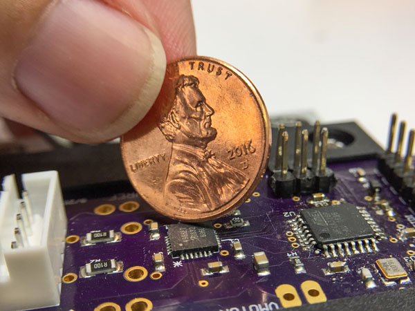 I had a board with a chip in a little QFN 28 package, and each pad was only 0.25 mm wide. The board wasn’t working. I really needed to figure out what was going wrong, but some of the important traces didn’t go though any exposed areas except at those tiny pads. How the heck was I going to probe this thing?
If I just went in with a scope probe, I was certain to short something out. I just don’t have a steady enough hand to poke around with sub 0.25 mm precision. That’s when it hit me. Engravers use something called a Pantographic Engraver to put the tiny lettering on wedding rings. Could I make some sort of Pantographic Probe to let me probe around the circuit willy-nilly with crazy precision? Yes. Yes, I could. That’s how the Pantoprobe was born.
You can build a Pantoprobe for < $20 if you have access to a 3D printer and a few hand tools. The project has even been featured on Hack-a-Day and Makezine!
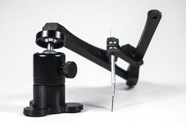
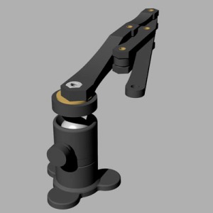
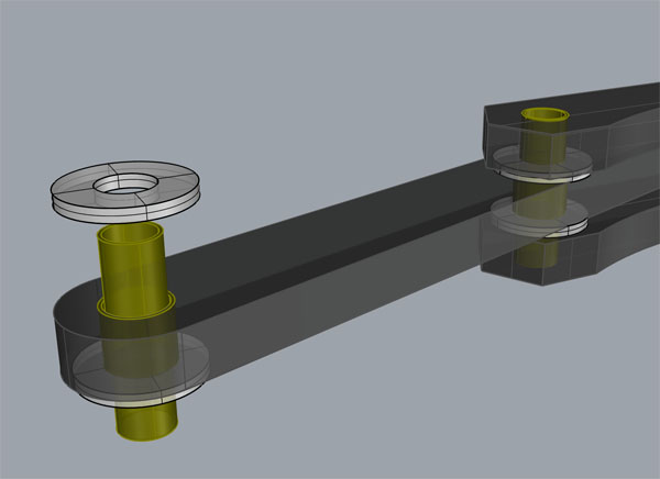 I hastily modeled a basic pantographic mechanism to 3D print. The one tricky part about a pantographic mechanism is that the joints have to have very little slop or stiction. I decided to use telescoping brass tubing at the hinge of each joint, with a pair of washers reducing vertical slope. I used a camera ball joint (that I had sitting around) as the base. This ball joint also lets you tilt the probe at different angles, providing an extra degree of freedom that most pantographs don’t have.
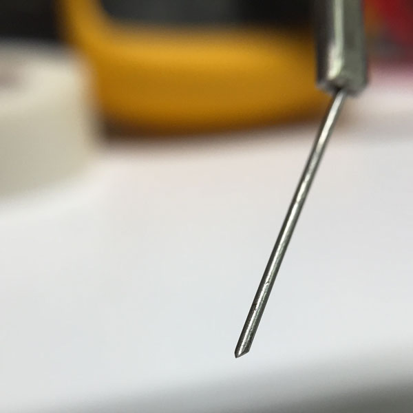
I printed a few test joints. The joint design seemed to work very smoothly, and I was ready to give the full assembly a try. What to use as the actual probe? I had some spring steel piano wire around, so I crimped a bit into another piece of tubing, ground a tapered pad on the end, and stuck the whole thing through the center of the pantograph’s output joint. That plus an alligator clip and it was time to take the probe for a test drive. Would it work?
I was amazed to discover that not only could I reliably place the probe on the center of the solder pigtail of those .25mm pads, but I could feel the probe pressing into the solder. Crazy! That tactile feedback really makes it nice to use. The contact is more than stable enough for me to look away long enough to read the oscilloscope/multi meter. Trouble shooting tiny boards will never be the same!
 I did some more designs to make the probe fold up more tightly so it could fit in my pack of trouble-shooting widgets. I also ordered some cheap ball joints from China since it seemed like I’d be making more of these things. The probe was a HUGE win: Cheap, not that hard to build, makes the impossible possible. What else could I do with this idea?
I could already do Pick and Place with tweezers, and it wasn’t a big problem. I had some parts sitting around for building a suction pick and place tool, but I’d never gotten around to building it because, hell, I could just do it with tweezers. What if I gave the Pantoprobe an extra-precise rotational axis and plumbed a suction tip into it? Would that be awesome? So I built this Pantographic Pick and Place device.
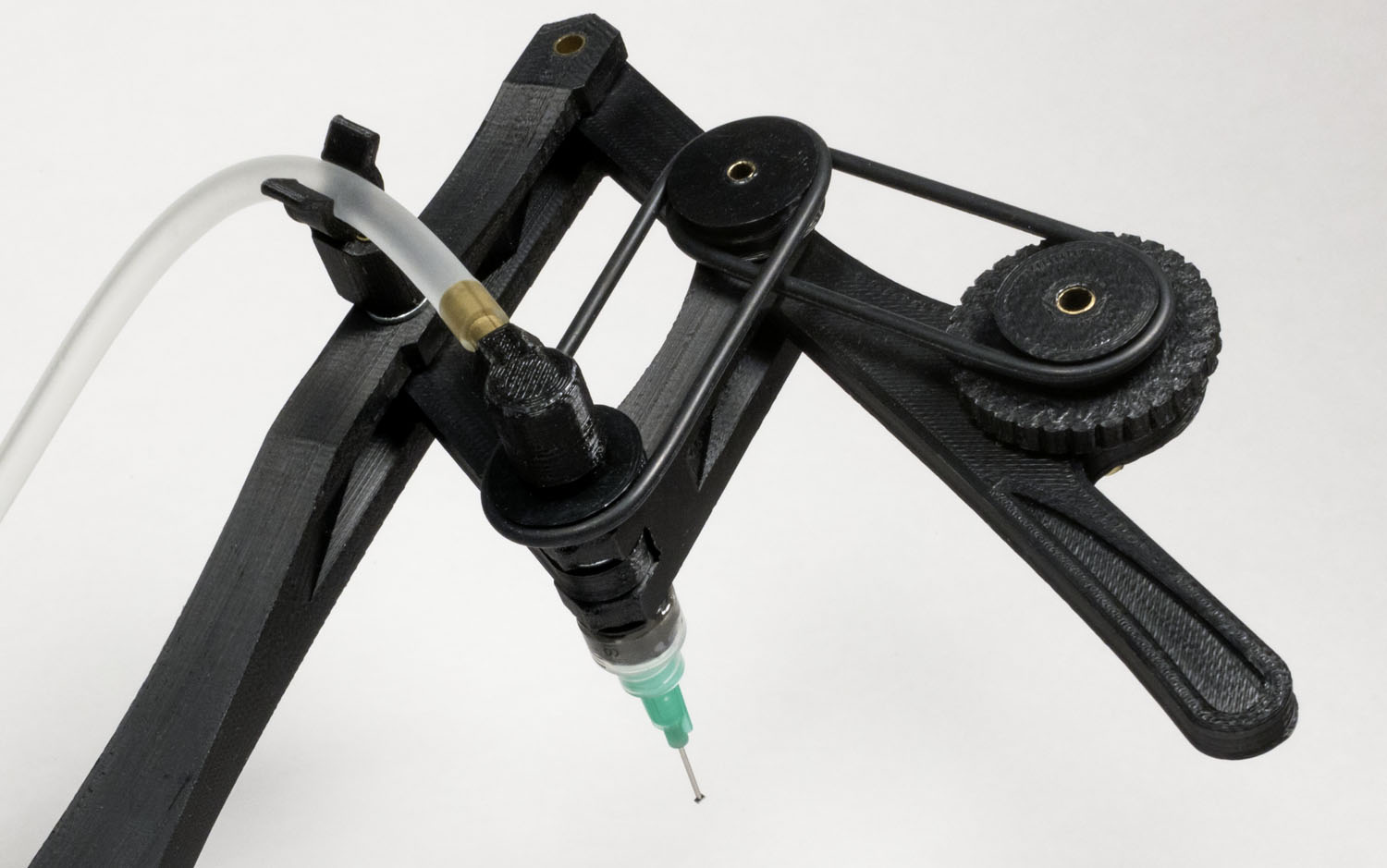
Now THAT looks like a actual mad science invention. I used two o-rings to act as drive belts for an index-finger controlled rotational axis. The suction comes in via a pivot that then passes though the pantographs output axis and comes out to a syringe with swappable tips. Here you can see a small green tip holding an 0603 resistor. This was a bit more complicated to design.
My 3D printer really got a workout. I printed 7 different versions of just the hose clip! I went crazy and even designed a box to hold all the tips. In the end, it works, it’s nice, but it doesn’t have quite the super high return on investment that the Pantoprobe has. It’s only two 0-rings and a syringe kit more expensive to build than the Pantoprobe. As long as you already have some system to provide suction.
If you do a lot of pick and place and would like a steadier hand, you should build one. But it doesn’t make the impossible possible like the Pantoprobe. That’s the real killer app.
What else?
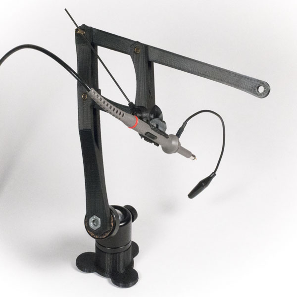
I realized that for measuring high frequency stuff the Kurt’s-random-piece-of-piano-wire sure left a lot to be desired. Maybe I could make a scope probe holder for the Pantoprobe?
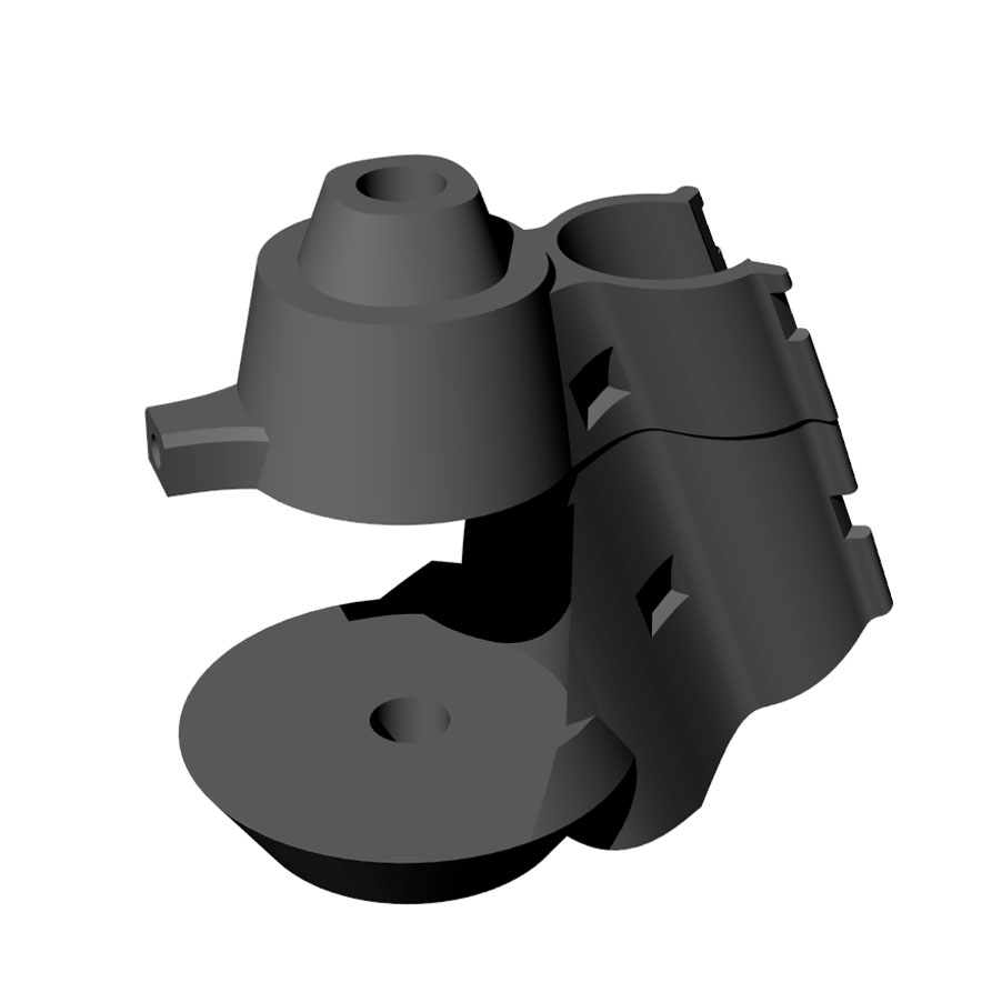 The scope probe was going to have to stick out at an angle so I could still see the end under the microscope. Because it would stick out a long way from the axis, I had to worry about rotational slop. So I designed this rod that slides from the output joint though the opposite joint to lock rotation. At first I thought of this as just an insert that pops into a stock Pantoprobe, but as I struggled to keep the probe from twisting/flexing, I realized I was going to need to do something that attached both at the top and bottom of the joint. I printed it in two pieces and glued them together, and I also glued them to the shaft that goes though the joint. There’s no removing that thing. I added two zip tie ports so the probe could be fully locked in if need be.
 Did it work? Sort of. Through my microscope I can’t see the actual tip, so you have to kind of think “the tip is right below the arc that is the side of the probe,” which kind of sucks. It wouldn’t be a problem if you’re just using an Opto-Visor instead of a scope. I also eventually figured out that my “clever” bar and tilted probe arrangement was reducing the precision multiplier of the pantograph, to something like 2x.
That plus the greater flex from the long probe extension makes the system less ridgid. It works, but the confidence factor/feel are not as good. Sometimes things slip. Another round of design on this one could make it stiffer and also increase the precision multiplier. I’ll have to see. This one is still very much a work in progress.
Maybe it would be smarter to make the piano wire probe into a more real probe in some way? Using 10:1 resistor divider and some coax cable, etc.
What else?
I thought maybe I could lock down the base so it’s easier to probe one handed. The great thing about using a 1/4-20 mounting nut is that I can use any sort of cheap camera mount. Luckily I’d ordered a suction cup mount when I’d gotten the ball mounts, so I was ready to give it a try.
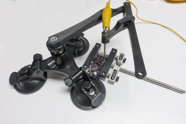 The bad news is it’s hard to get your board in close enough with all those suction cups taking up space. The good news is that one-handed operation is reasonable with this setup. Two-handed usage makes it easier to hop large distances, and feels a bit more fluid but one-handed works.
I tried using my Third Hand to hold the probe locked on some test point, but it was infuriating. It really just didn’t work at all. Trying to position it was a mystery of over shooting and undershooting. A true fail. I was beginning to think maybe a fully locked test point wasn’t going to be a thing I’d be able to do. Then I realized I was over thinking the problem. I discovered that with a bit of technique you could lock the ball joint with the probe just a bit above where you wanted it, and then you could position it and the weight of the probe would hold it in place. Woot! Now you don’t exactly want to dribble a basket ball next to the “locked” probe, but it’s better than “you can’t do that,” and for bigger/safer test targets like a via I’d say it is safe enough. Still the rig is kind of huge. Maybe a smaller suction cup base would make it a lot better.
What’s next? Maybe an Exact-O blade tip for cutting traces? A higher precision multiplier one for people with shaky hands? A Dremel tool holding one? A soldering iron one? I think there are a lot of other good ideas hovering around this one. Build yourself a Pantoprobe. Give it a try. You won’t regret it!
Where do you go from here?
I feel like this is an important invention. Looking around, I didn’t see anyone making a product like this which is kind of crazy. So I’ve done a lot of work to get the word out. I have the basic PantoProbe models on github. I made a video explaining the probe and another showing you how to assemble one. I set up pantoprobe.com to have a central place to point people, and where people can share ideas.
After building quite a few of these probes I also realized that there should be a simpler version of the probe that doesn’t have the complicated joints. A very simple flexure based model. So I developed the PantoFlex. It doesn’t have the same range of motion as a full on probe, but it is almost trivial to print and use. I also make it come apart so it could be printed on some of the smaller 3D Printers.
Get out there and try one!


Pingback: How To Build a PantoProbe – PantoProbe
Pingback: Precision Pantograph Probes PCBs | Hackaday
Pingback: Precision Pantograph Probes PCBs – High Tech Newz
Great work. Could you please post the scope probe holder to github?
Well if you read the post, that probe clipping design is still a work in progress. You can’t see where the tip is, it flexes too much to be that useful, etc. It’s still quite iffy. I don’t want people getting their first impression of pantographic probing from THAT design. I’m currently working on a probe clipping version based on the flexible PantoProbe design with a closer grip/lower angle + higher precision multiplier. That should be both easier to put together and miles better than the current clipped probe design. Hopefully I can get that working and posted fairly soon. I’m working hard to get people to recognize how useful a pantographic probe is. The last thing I want is for early adopters to put in a bunch of time building something that isn’t that useful! I’m going to put an improved PantoFlex version up on github today. (5x multiplier and twist lock) Hopefully I can get the improved high freq. probe design ironed out in the next few weeks.
Pingback: Troubleshoot Your Electronics with an Open-Source PantoProbe | #makertools « Adafruit Industries – Makers, hackers, artists, designers and engineers!
Howdy… Just printed the Pantoflex… what’s the knob for?
The knob snaps onto the little cylindrical shaft. Then you can twist it to lock/unlock the probe’s central metal shaft. (The knob and the cylinder have eccentric holes so they are unlocked when those line up.) I’m excited you’re building a probe!